Device and method for driving LED

a technology of led lighting and diodes, which is applied in the direction of electrical equipment, electrical variable regulation, instruments, etc., can solve the problems of large power consumption at current-limiting resistors, and large device size and weight, and achieves simple constitution, high power efficiency, and small size

Active Publication Date: 2009-07-21
AVAGO TECH INT SALES PTE LTD
View PDF2 Cites 110 Cited by
  • Summary
  • Abstract
  • Description
  • Claims
  • Application Information

AI Technical Summary

Benefits of technology

[0011]Therefore, an object of the present invention is to provide an LED lighting device and a lighting method thereof, which have high power efficiency and do not require a particular anti-noise measure. Another object of the present invention is to provide an LED lighting device having a smaller size and a simple constitution (thus inexpensive) without a capacitor having a large voltage and a large capacity, a power transformer, and a DC / DC converter.
[0012]The present invention provides an LED lighting device, which lights an LED array comprised of a plurality of series-connected LEDs by an AC power, which selectively controls lighting or lighting-out of each LED of the LED array depending on the magnitude of AC source voltage thereby to efficiently utilize AC source.
[0013]According to one embodiment of the present invention, a signal voltage (hereafter “rectified voltage”) obtained by rectifying an AC source is compared with a predetermined reference voltage. When the AC source voltage is larger than the reference voltage, more LEDs are lit up. When it is smaller, less LEDs are lit up. In this case, it is preferable to light up such a maximum number of LEDs that can be lit up by the source voltage at any given point in time in order to efficiently utilize a power source.
[0014]The present invention can provide an LED lighting device with high power efficiency. Further, the present invention can provide such an LED lighting device with a more reduced size at a lower cost without taking a particular anti-noise measure.

Problems solved by technology

In the conventional constitution as shown in FIG. 8, the capacitor 404 with a high voltage and a large capacity has to be used to supply a voltage higher than the total sum of forward voltages of LEDs, disadvantageously resulting in a larger and expensive device.
Thus, a disadvantage with the device is that power consumption at the current-limiting resistor is large.
In the conventional constitution as shown in FIG. 9, the device has a large size and weight and is expensive due to the provision of the power transformer.
Further, the device has a problem in that power consumption at the current-limiting resistor is still large.
However, in addition to the DC / DC converter having a transformer built-in, an EMI filter for suppressing noises generated by the DC / DC converter is required, disadvantageously resulting in a larger and expensive device.
As described above, all of the LED lighting devices according to prior art cannot simultaneously solve both problems in terms of size / cost and power efficiency.
The problem of power efficiency becomes particularly serious when a lighting system using white LEDs is designed as an alternative to an electric bulb or a fluorescent lamp.

Method used


Image

  • Device and method for driving LED
  • Device and method for driving LED
  • Device and method for driving LED

Examples


first embodiment

1. First Embodiment

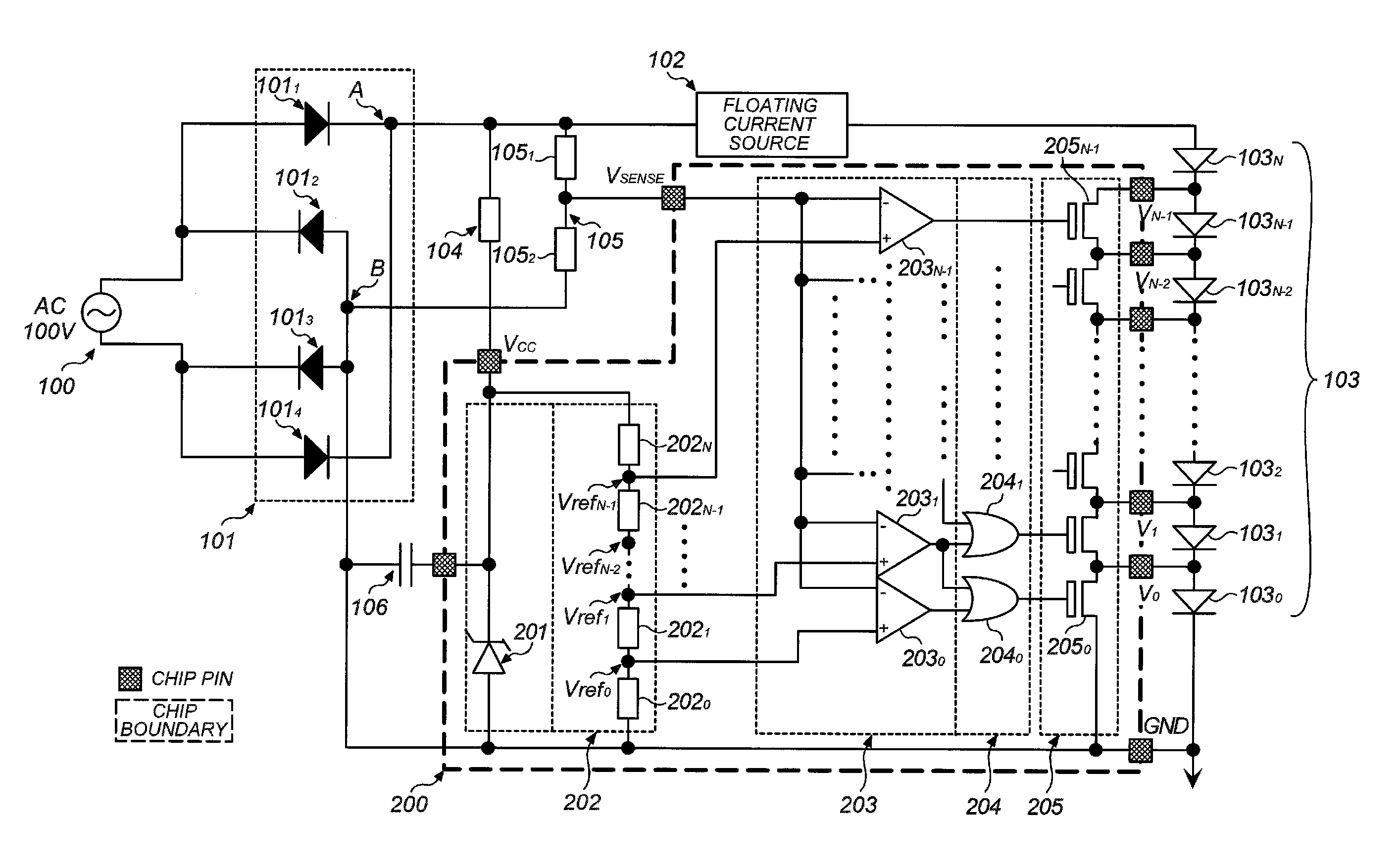
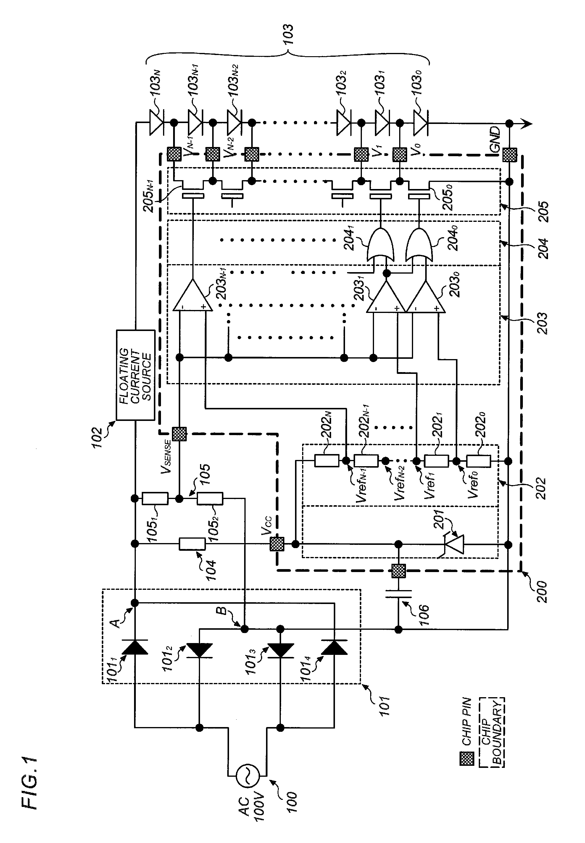
[0040]Hereafter, a first embodiment of the present invention is described by referring to FIG. 1. FIG. 1 is a schematic block diagram of an LED lighting device according to the first embodiment of the present invention.

[0041]An AC source 100 and a rectifier circuit 101 in FIG. 1 may be similar to those of conventional constitutions shown in FIGS. 8 to 10. As the AC source for an LED lighting device, a commercial source (having, for example, 100V to 220V and 50 Hz to 60 Hz) is generally used in consideration general versatility, but an AC source other than a commercial source may be used. Use of a single-phase AC source is assumed in this embodiment, but three-phase AC, etc. may be used as the source.

[0042]Numeral 101 denotes a full-wave rectifier circuit comprised of four rectified diodes 1011, 1012, 1013, and 1014, which rectifies a commercial AC source to output a rectified voltage waveform, as exemplified in FIG. 4, between a plus output terminal A and a minus ...

second embodiment

2. Second Embodiment

[0068]Next, a second embodiment of the present invention is described by referring to FIG. 7. This embodiment has a constitution equivalent to one shown in FIG. 1 except that LEDs are arranged in parallel and a lighting LED selection circuit 204 and a switch circuit 205 are modified to a control logic circuit 204′ and a switch circuit 205′. Thus, the remaining parts of this embodiment are the same as those shown in FIG. 1.

[0069]In FIG. 7, LEDs 103′0-1 to 103′(N−1)−3 are divided into N number of blocks each having three LEDs as indicated by dotted frames. These blocks include block 0 comprised of 103′0-1, 103′0-2, and 103′0-3; block 1 comprised of 103′1-1, 103′1-2, and 103′1-3; likewise, block 2, block 3, . . . , block (N−2); and finally block (N−1) comprised of 103′(N−1)−1, 103′(N−1)−2, and 103′(N−1)−3. N represents an integer of not less than 1, which can be properly set depending on embodiment requirement.

[0070]In this embodiment, LEDs of each block are connect...


PUM


Abstract

An LED lighting device of AC power-driven type having a comparatively simple constitution and a high power efficiency. The device compares a signal voltage (rectified voltage) obtained by rectifying an AC source with a predetermined reference voltage and controls ON / OFF of a driving current to each LED of an LED array in response to a comparison result. In this constitution, a large voltage of AC source enables lighting of more number of LEDs, while a small voltage thereof enables lighting of less number of LEDs, thus enhancing power efficiency of the LED lighting device.

Description

CROSS REFERENCE TO RELATED APPLICATION[0001]This application is entitled to the benefit of Japanese Patent Application Number 2006-232786, filed on Aug. 29, 2006, the disclosure of which is incorporated herein by reference.FIELD OF THE INVENTION[0002]The present invention relates to a light emitting diode (LED) lighting device, and particularly to an LED lighting device suitable for a lighting system and a lighting method thereof.BACKGROUND OF THE INVENTION[0003]A constitutional example of a conventional LED drive unit, which drives an LED by a commercial AC source and is applicable to a lighting system, is described by referring to the drawings.[0004]FIG. 8 is a schematic view showing one embodiment of an LED lighting device according to prior art. In the figure, there are provided a commercial AC source 400; a full-wave rectifier circuit 401 comprised of rectifier diodes 4011 to 4014 for rectifying the commercial AC source; a current-limiting resistor 402 connected to a plus outpu...

Claims


Application Information

Patent Timeline
Patent Type & Authority Patents(United States)
IPC IPC(8): H05B37/00H05B44/00
CPCH05B33/0803H05B33/0815H05B33/0809H05B33/0866H05B33/083Y02B20/347H05B45/24H05B45/37Y02B20/30H05B45/44H05B45/40H05B45/30H05B45/48
Inventor YAMAMOTO, KENJIKEONG, RICHARD LUM KOK
Owner AVAGO TECH INT SALES PTE LTD
Why Eureka
Try Eureka