
Reproducing apparatus

a technology of re-creation apparatus and disk, which is applied in the direction of digital signal error detection/correction, instruments, recording signal processing, etc., can solve the problems of increasing circuit size and cost, obtaining a stable clock, etc., and achieve the effect of facilitating the stable rotation of the disk

Inactive Publication Date: 2009-07-21
CANON KK
View PDF12 Cites 0 Cited by
  • Summary
  • Abstract
  • Description
  • Claims
  • Application Information

AI Technical Summary

Benefits of technology

The solution allows for a stable clock generation and accurate address information detection without enlarging the circuit, improving disk rotation stability and reducing costs by eliminating the need for redundant PLL circuits and addressing temperature-related frequency changes.

Problems solved by technology

Thus, problems of increases in circuit size and costs have inevitably occurred.
Furthermore, unevenness in temperature characteristics, or processes between the two PLL circuits can cause a change in clock frequency, creating a problem in reliably obtaining a stable clock.

Method used


Image

  • Reproducing apparatus
  • Reproducing apparatus
  • Reproducing apparatus

Examples


Embodiment Construction

[0021]The following description of exemplary embodiment(s) is / are merely illustrative in nature and is in no way intended to limit the invention, its application, or uses.

[0022]Processes, techniques, apparatus, and materials as known by one of ordinary skill in the art may not be discussed in detail but are intended to be part of the enabling description where appropriate. For example certain circuitry for a phase comparator, loop filter, frequency divider, phase detector and others may not be discussed in detail. However these systems and the methods to fabricate these system as known by one of ordinary skill in the relevant art is intended to be part of the enabling disclosure herein where appropriate.

[0023]Note that similar reference numerals and letters refer to similar items in the following figures, and thus once an item is defined in one figure, it may not be discussed for following figures.

[0024]Exemplary embodiments will be described in detail below with reference to the dr...


PUM

PropertyMeasurementUnit
frequencyaaaaaaaaaa
frequencyaaaaaaaaaa
clock frequenciesaaaaaaaaaa

Abstract

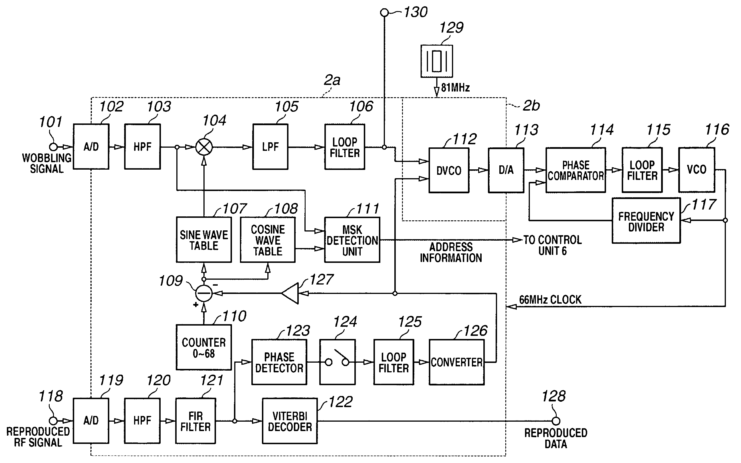
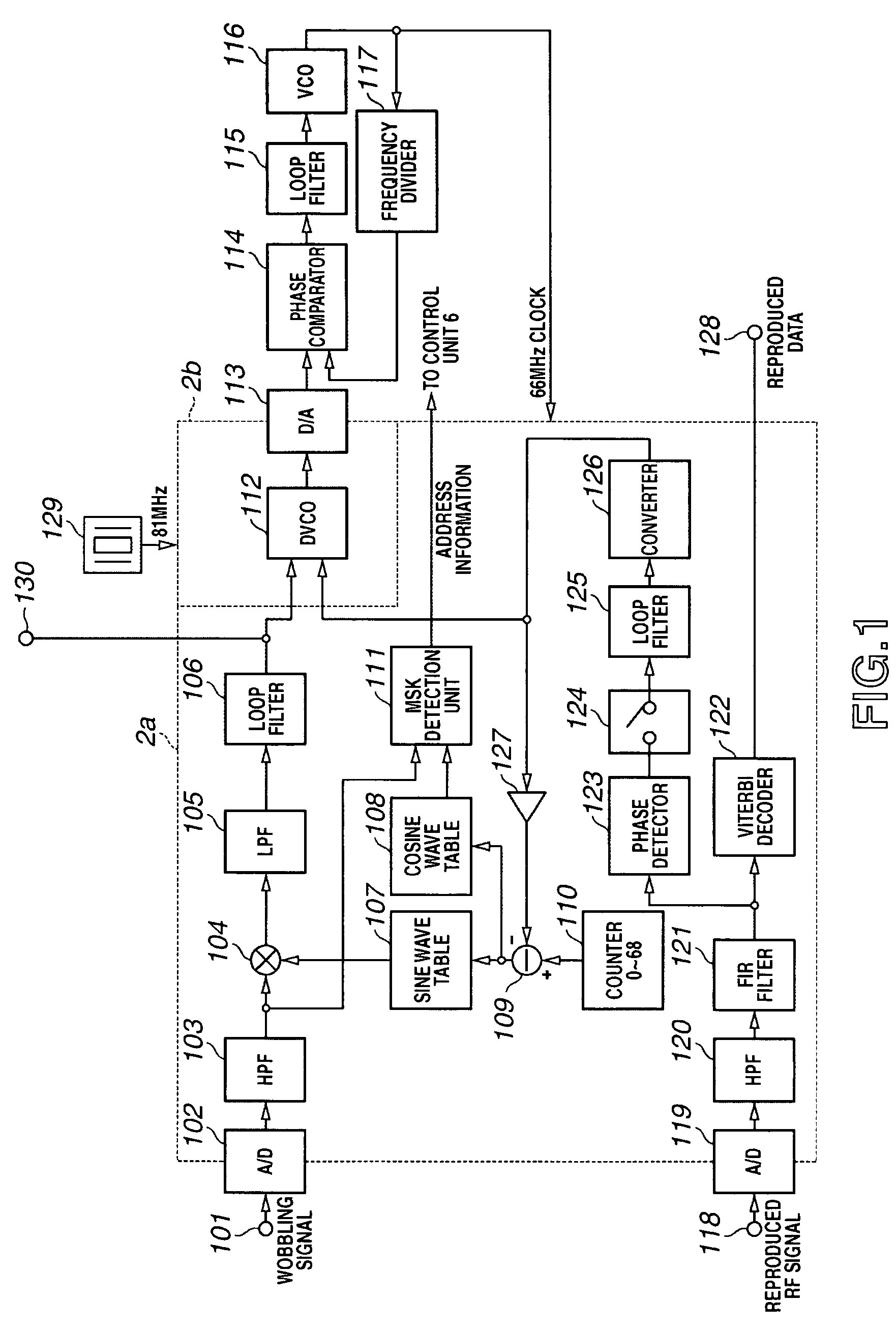
A reproducing apparatus includes a reading unit configured to generate a reproduced signal containing information data recorded in a track using a reflected light of an optical beam, a clock generation unit configured to generate a clock having a frequency associated with a wobbling cycle of the track, and a control unit configured to detect a phase difference between the reproduced signal and the clock, and to control the clock generation unit using the phase difference detection result.

Description

BACKGROUND OF THE INVENTION[0001]1. Field of the Invention[0002]The present invention relates to a reproducing apparatus, and more particularly, though not exclusively, to an apparatus for reproducing data from a disk recording medium.[0003]2. Description of the Related Art[0004]A high-density optical disks (e.g., a digital versatile disk (DVD) or a blu-ray disk) have been developed conventionally.[0005]In a disk of this type, a groove is spirally formed thereon, and an optical beam is applied using this groove as a recording / reproducing track to write / read information. To superimpose addresses on the disk or to obtain a clock during reproduction, the groove is formed beforehand wobbling in a fixed cycle on the disk. When performing reproduction, an optical beam is applied to this wobbling track. From its reflected light, a clock associated with the wobbling cycle is generated, and address information is read. A clock, synchronized in phase with information contained in the reflecte...

Claims


Application Information

Patent Timeline
Patent Type & Authority Patents(United States)
IPC IPC(8): G11B7/005
CPCG11B7/0053G11B7/0045
Inventor TANAKA, YASUYUKIYAMASHITA, SHINICHI
Owner CANON KK
Learn More