Magnetic suspension turntable and dining table

A magnetic levitation and turntable technology, which is applied in the direction of the table, table, and the legs of general furniture where the table top can be rotated on the vertical axis, which can solve the problems of inflexibility of the turntable, large force on the turntable, and rollover.

Pending Publication Date: 2022-03-01
严继威
View PDF0 Cites 0 Cited by
  • Summary
  • Abstract
  • Description
  • Claims
  • Application Information

AI Technical Summary

Problems solved by technology

At present, most of the table turntables used on the market are connected to the base with rolling bearings to achieve rotation. However, if the dishes are placed unevenly, the force on one side of the turntable will be too large, which will easily cause rollover. As a result, the inflexible rotation of the turntable makes the friction force gradually increase, and the turntable becomes more and more inflexible, or even unable to rotate, so it needs to be replaced, which increases the cost. This problem needs to be solved urgently.

Method used


Image

  • Magnetic suspension turntable and dining table
  • Magnetic suspension turntable and dining table
  • Magnetic suspension turntable and dining table

Examples


Embodiment 1

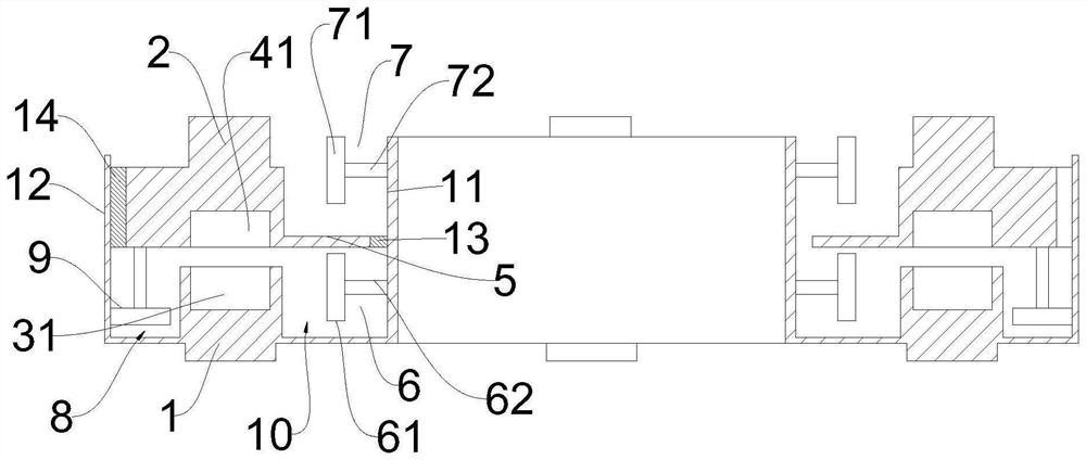
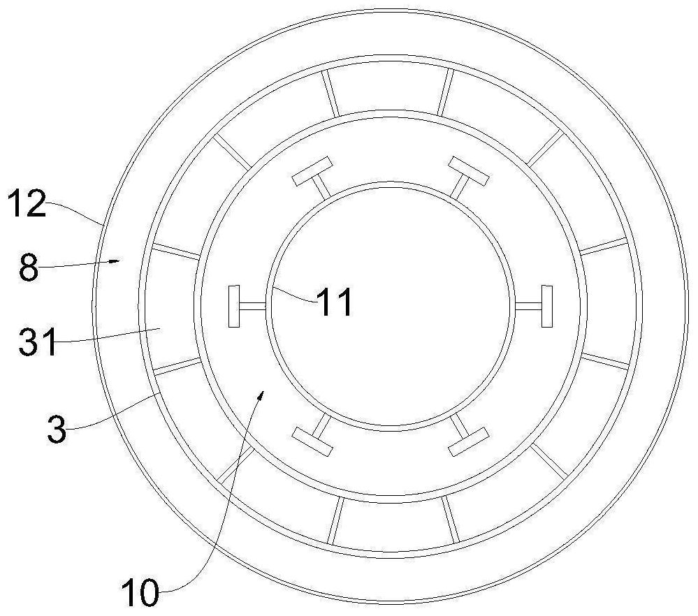
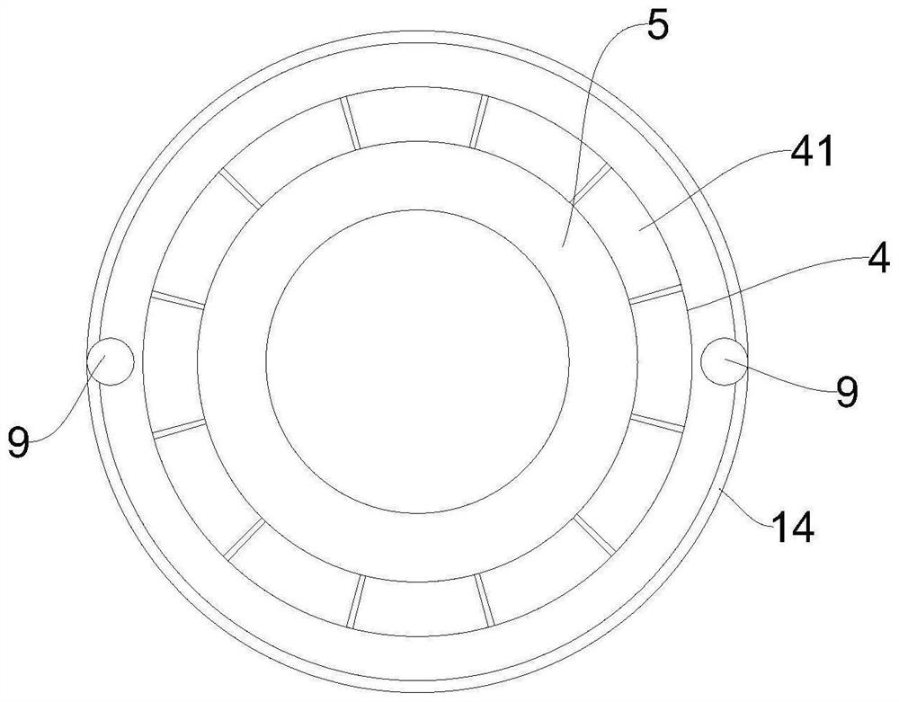
[0035] Such as Figure 1-3As shown, this embodiment provides a magnetic levitation turntable, including a levitation turntable 2 and a support plate 1, the levitation turntable 2 is arranged above the support plate 1, the upper end of the support plate 1 is provided with a first ring magnet 3, and the levitation turntable 2 The lower end is provided with a second ring magnet 4, the inner diameter of the first ring magnet 3 and the second ring magnet 4 are the same, and the magnetic poles of the adjacent ends are opposite; An upper limit assembly and a lower limit assembly are arranged on the top, the above-mentioned annular limit plate 5 is located between the above-mentioned upper limit assembly and the above-mentioned lower limit assembly, and the upper end of the above-mentioned lower limit assembly is located above the above-mentioned first ring magnet 3 .

[0036] In this embodiment, the suspension turntable 2 is separated from the support disk 1 through the repulsion of ...

Embodiment 2

[0038] Such as Figure 1-3 As shown, in this embodiment, on the basis of Embodiment 1, the above-mentioned lower limit assembly includes a plurality of first rotating devices 6, and the circumference of the plurality of above-mentioned first rotating devices 6 is arranged on the above-mentioned support plate 1; the above-mentioned annular limit plate 5 When moving downwards and contacting the first rotating device 6 , the above-mentioned annular limiting plate 5 is rotationally connected with the above-mentioned first rotating device 6 .

[0039] In this embodiment, when the sum of the gravity of the suspended turntable 2 and the gravity of the placed objects on it is greater than the repulsive force of the first ring magnet 3 and the second ring magnet 4, the above-mentioned ring-shaped limiting plate 5 moves downward to match the above-mentioned first ring magnet. When the rotating device 6 contacts, the above-mentioned annular limiting plate 5 is rotationally connected with...

Embodiment 3

[0043] Such as Figure 1-3 As shown, this embodiment is based on some of the above-mentioned embodiments, the above-mentioned upper limit assembly includes a plurality of second rotating devices 7, and the circumference of the above-mentioned second rotating devices 7 is set on the above-mentioned suspension turntable 2; the above-mentioned annular limit plate 5 moves upwards and contacts with the second rotating device 7, the above-mentioned annular limiting plate 5 is rotationally connected with the above-mentioned second rotating device 7.

[0044] In this embodiment, when the sum of the gravity of the suspended turntable 2 and the gravity of the placed objects on it is less than the repulsive force of the first ring magnet 3 and the second ring magnet 4, the upward movement of the above-mentioned ring-shaped limiting plate 5 and the above-mentioned second rotation When the device 7 is in contact, the above-mentioned annular limiting plate 5 is rotationally connected with t...


PUM


Abstract

The invention provides a magnetic suspension turntable and a dining table, and relates to the technical field of turntables. A magnetic suspension rotating disc comprises a suspension rotating disc body and a supporting disc, the suspension rotating disc body is arranged above the supporting disc, a first annular magnet is arranged at the upper end of the supporting disc, a second annular magnet is arranged at the lower end of the suspension rotating disc body, the first annular magnet and the second annular magnet are consistent in inner diameter, and the magnetic poles of the ends, close to each other, of the first annular magnet and the second annular magnet are opposite; an annular limiting plate is arranged on the suspension rotating disc, an upper limiting assembly and a lower limiting assembly are arranged on the supporting disc, the annular limiting plate is located between the upper limiting assembly and the lower limiting assembly, and the upper end of the lower limiting assembly is located above the first annular magnet; when the turntable rotates, the friction force is smaller, the rotation is flexible and stable, and the service life is longer.

Description

technical field [0001] The invention relates to the technical field of turntables, in particular to a magnetic levitation turntable and a dining table. Background technique [0002] Table turntables have been widely used in restaurants and hotels, and are gradually being used in family gatherings. At present, most of the table turntables used on the market are connected to the base with rolling bearings to achieve rotation. However, if the dishes are placed unevenly, the force on one side of the turntable will be too large, which will easily cause rollover. As a result, the inflexible rotation of the turntable makes the friction force gradually increase, and the turntable becomes more and more inflexible, or even unable to rotate, so it needs to be replaced and the cost is increased. This problem needs to be solved urgently. Contents of the invention [0003] The object of the present invention is to provide a magnetic levitation turntable, which has smaller frictional fo...

Claims


Application Information

Patent Timeline
Patent Type & Authority Applications(China)
IPC IPC(8): A47B11/00A47B13/08A47B13/00H02N15/00
CPCA47B11/00A47B13/08A47B13/00H02N15/00
Inventor 严继威
Owner 严继威
Why Eureka
Try Eureka