Side light-emitting device, backlight unit having the side light-emitting device, and liquid crystal display apparatus employing the backlight unit

a backlight unit and side light technology, applied in the field of backlight units having the side light emitting devices, and liquid crystal display devices employing the backlight units, can solve the problems of difficult manufacturing the sawtooth-shape side portion of the conventional side emitter is difficult to manufacture, and the conventional side-emitter b>1/b> does not meet this requirement, etc., to achieve the effect of easy manufacturing

Inactive Publication Date: 2009-07-28
SAMSUNG ELECTRONICS CO LTD
View PDF24 Cites 61 Cited by
  • Summary
  • Abstract
  • Description
  • Claims
  • Application Information

AI Technical Summary

Benefits of technology

[0015]The present general inventive concept provides a side light-emitting device that is easy to manufacture and spreads light over a wide area, a slim backlight unit that uses the side light-emitting device as a light source, and a liquid crystal display (LCD) apparatus employing the backlight unit.
[0026]The backlight unit may further include at least one of a brightness enhancement film (BEF) to improve a directionality of light beams passing through the first transmissive diffusion plate, and a polarization enhancement film to increase efficiency of polarization.

Problems solved by technology

However, the sawtooth-shape side portion of the conventional side emitter is difficult to manufacture. FIG. 1 illustrates the conventional side emitter 1 (described above).
However, the side-emitting LED having the conventional side-emitter 1 does not satisfy this requirement.
Another drawback of the side-emitting LED having the conventional side-emitter 1 is that it is difficult to manufacture due to the complicated structure including the reflecting surface 3, the first refracting surface 5, and the second curved refracting surface 7.

Method used


Image

  • Side light-emitting device, backlight unit having the side light-emitting device, and liquid crystal display apparatus employing the backlight unit
  • Side light-emitting device, backlight unit having the side light-emitting device, and liquid crystal display apparatus employing the backlight unit
  • Side light-emitting device, backlight unit having the side light-emitting device, and liquid crystal display apparatus employing the backlight unit

Examples


Embodiment Construction

[0040]Reference will now be made in detail to the embodiments of the present general inventive concept, examples of which are illustrated in the accompanying drawings, wherein like reference numerals refer to the like elements throughout. The embodiments are described below in order to explain the present general inventive concept while referring to the figures.

[0041]A side light-emitting device, a backlight unit that uses the side light-emitting device as a light source, and a liquid crystal display (LCD) apparatus employing the backlight unit according to various embodiments of the present general inventive concept will now be described with reference to the accompanying drawings.

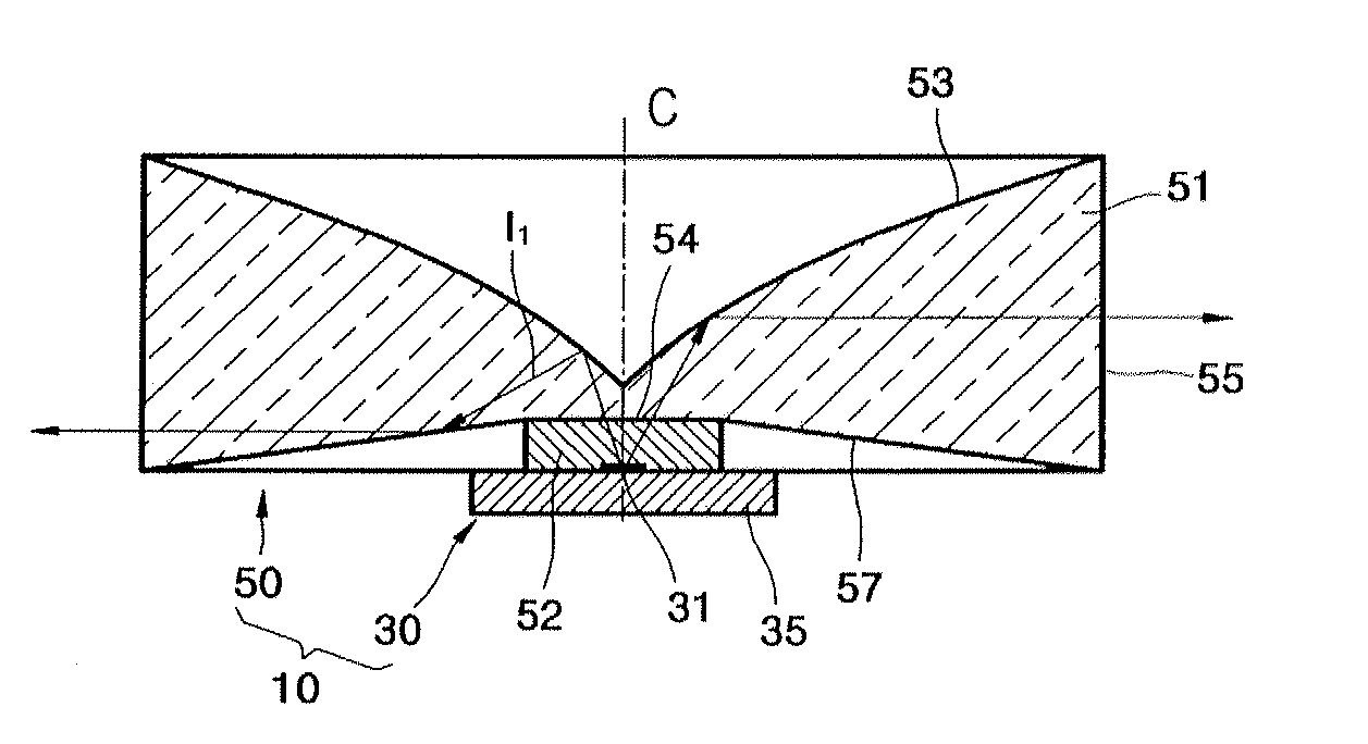
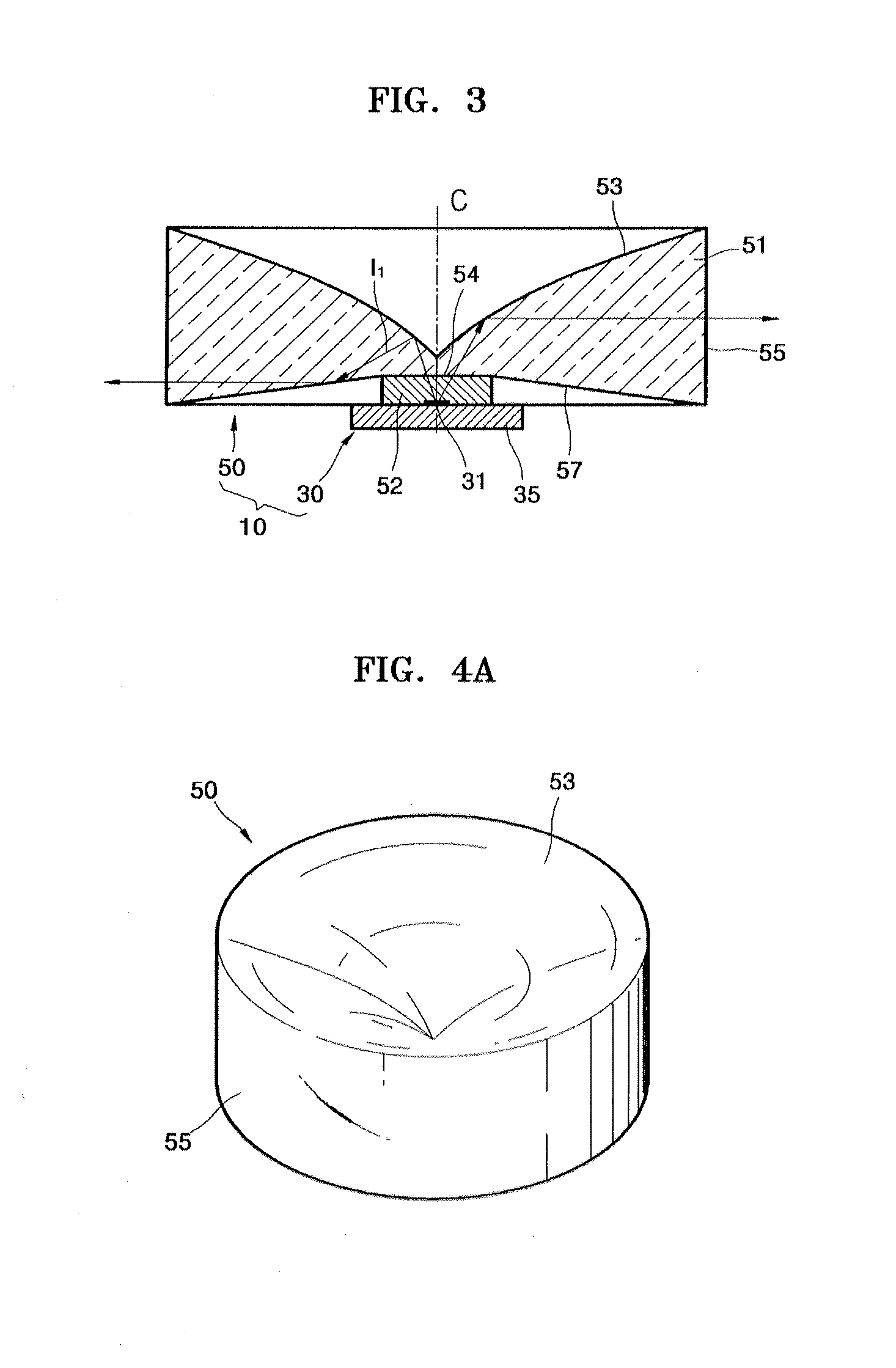
[0042]Referring to FIGS. 3 and 4B, a side light-emitting device 10 according to an embodiment of the present general inventive concept includes a light-emitting device 30 to generate light and a side emitter 50 to emit the generated light incident from the light-emitting device 30 in a lateral direction.

[...


PUM


Abstract

A side light-emitting device including a light-emitting device to generate light and a side emitter to emit the light incident from the light-emitting device in a lateral direction. The side emitter includes a first reflecting surface to reflect the light emitted from the light-emitting device into the side emitter, a second reflecting surface that is formed at a portion of the side emitter that contacts the light-emitting device to reflect a first light that is reflected from the first reflecting surface in the lateral direction, and a refracting surface to refract a second light that is reflected from the first reflecting surface and proceeding directly toward the refracting surface and the first light that is reflected from the first reflecting surface to the second reflecting surface and is reflected again from the second reflecting surface to exit the side emitter in the lateral direction.

Description

CROSS-REFERENCE TO RELATED APPLICATIONS[0001]This application claims the benefit of Korean Patent Application No. 2004-97022, filed on Nov. 24, 2004, in the Korean Intellectual Property Office, the disclosure of which is incorporated herein in its entirety by reference.BACKGROUND OF THE INVENTION[0002]1. Field of the Invention[0003]The present general inventive concept relates to a side light-emitting device, a backlight unit that uses the side light-emitting device as a light source, and a liquid crystal display (LCD) apparatus employing the backlight unit.[0004]2. Description of the Related Art[0005]An LCD is a passive flat panel display that uses an external light source to produce an image. A backlight unit is used as the external light source and is located behind the LCD and emits light.[0006]Backlight units can be classified as direct light type backlight units or edge light type backlight units according to a position of the light source. In the direct light type backlight u...

Claims


Application Information

Patent Timeline
Patent Type & Authority Patents(United States)
IPC IPC(8): F21V7/00F21V5/00F21V5/04H01L33/44H01L33/46H01L33/60
CPCH01L33/54G02F1/133603G02F1/1335
Inventor NOH, JI-WHANKIM, DONG-HA
Owner SAMSUNG ELECTRONICS CO LTD
Why Eureka
Try Eureka