

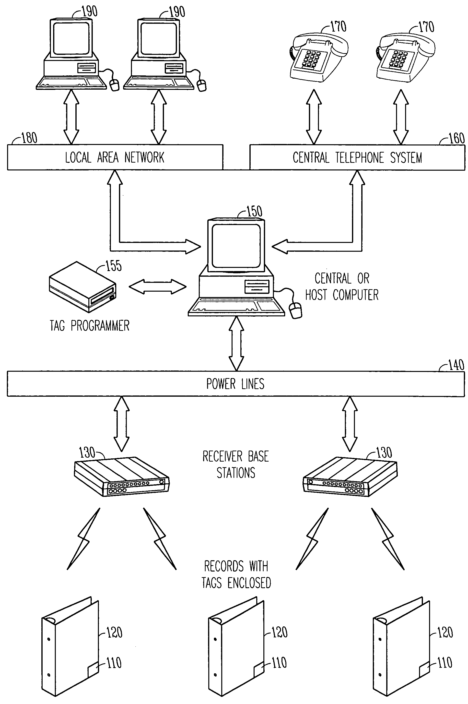
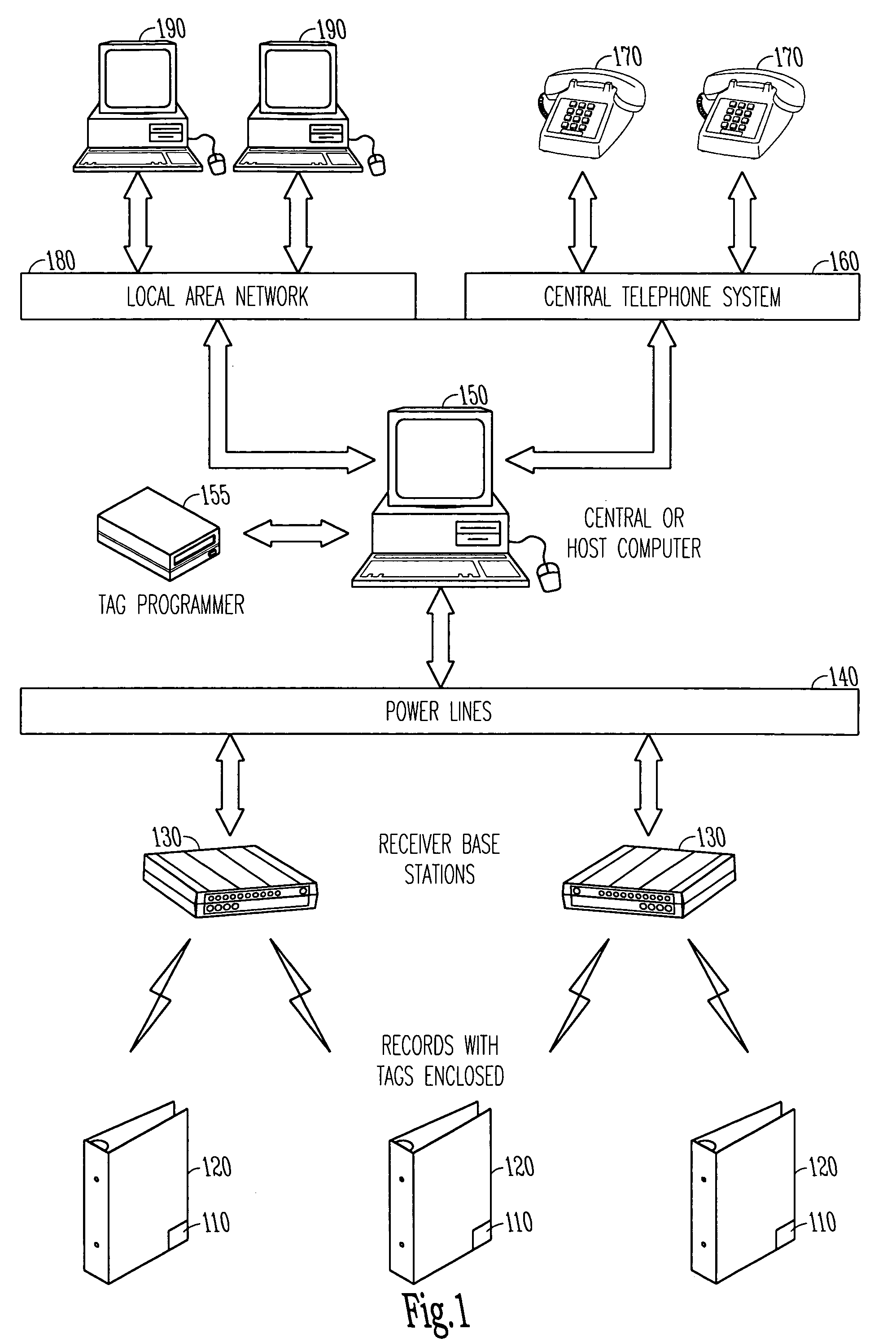
Wide area multipurpose tracking system
a multi-purpose, tracking system technology, applied in direction finders using radio waves, instruments, electric signalling details, etc., can solve the problems of ineffective locating of present-day record keeping systems, inability to provide medical care, and high cost and time dedicated to finding objects, so as to avoid overlap of transmissions, reduce problems, and prolong the life of each transmitter
- Summary
- Abstract
- Description
- Claims
- Application Information
AI Technical Summary
Benefits of technology
Problems solved by technology
Method used
Image

Examples
example 1
[0055]given: record 234123 is associated with Tag E.
[0056]>Search for record: 234123
[0057]>Which Tag is associated with record 234123[0058]Tag E (given)
[0059]>List all RBSs with Tag E (list A) (see FIG. 5B)[0060]RBS 1[0061]RBS 2[0062]RBS 3
[0063]>List all rooms that are common to RBS 1, RBS 2, RBS 3 (list B)[0064]Room 147 [Report Possible locations]
[0065]>List all RBS not with Tag E (list C)[0066]
[0067]>List All rooms from previous list (list D)[0068]
[0069]>List all rooms in list B and not in list D[0070]Room 147[0071][Report identified location]
[0072]>The record is in room 147
example 2
[0073]given: record 235555 is associated with Tag B.
[0074]>Search for record: 235555
[0075]>Which Tag is associated with record 235555[0076]Tag B
[0077]>List all RBS with Tag B (list A)[0078]RBS 2[0079]RBS 3
[0080]>List all rooms that are common to RBS 2, RBS 3 (list B)[0081]Room 142[0082]Room 147[0083][Report possible locations]
[0084]>List all RBS not with Tag B (list C)[0085]RBS 1
[0086]>List all Rooms from list C (list D)[0087]Room 146[0088]Room 147[0089]Room 148[0090]Room 149[0091]Room 150
[0092]>List all rooms in list B and not in list D[0093]Room 142 [Report identified location]
[0094]>The record is in room 142
example 3
[0095]given: record 235335 is associated with Tag D.
[0096]>Search for record: 235335
[0097]>Which Tag is associated with record 235335[0098]Tag D
[0099]>List all RBS with Tag D (list A)[0100]RBS 1[0101]RBS 2
[0102]>List all rooms that are common to RBS 1, RBS 2 (list B)[0103]Room 146[0104]Room 147[0105][Report possible locations]
[0106]>List all RBSs not with Tag D (list C)[0107]RBS 3
[0108]>List all Rooms from list C (list D)[0109]Room 142[0110]Room 143[0111]Room 144[0112]Room 147[0113]Room 150[0114]Room 151
[0115]>List all rooms in list B and not in list D[0116]Room 146[0117][Report identified location]
[0118]note: that this identified location is not correct (see FIG. 4)
[0119]>The record is in room 146
Note that the last example gave a wrong identified location. This can be remedied by dividing certain rooms up into more reception ranges. For example room 147 can be broken up into two reception regions 147a and 147b.
PUM
 Abstract
Description
Claims
Application Information