Saw blade

a technology of saw blades and blades, applied in the field of saw blades, can solve the problems of prone to breakage, excessive cutting, and easy to break teeth, and achieve the effect of easy cutting a solid material and a pipe material

Inactive Publication Date: 2009-08-04
AMADA CO LTD
View PDF20 Cites 31 Cited by
  • Summary
  • Abstract
  • Description
  • Claims
  • Application Information

AI Technical Summary

Benefits of technology

[0039]Therefore, it is possible to easily cut a solid material and a pipe material, and to carry out t...

Problems solved by technology

When a pipe material P having a diameter of 50 mm and a thickness of 3 mm is cut using the same saw blade 101 as shown in FIG. 4, however, there is a problem that the saw blade 101 is prone to be broken off.
This is because that although the pitch of the saw blade 101 is 4 mm, the thickness of the pipe material P is 3 mm and the cutting speed of the saw blade 101 is close to a free fall of a housing load G and thus, if the cutting operation by the saw blade 101 reaches near the center of the pipe material P in this cutting condition, the workpiece P enters between a tip and a tip of the saw blade 101, and abrupt free fall is generated, a cutting amount becomes excessively increased and thus, the teeth are prone to be broken.
Therefore, there is a problem that the cutting time becomes long as compared with a case i...

Method used


Image

  • Saw blade
  • Saw blade
  • Saw blade

Examples


first embodiment

[0072]Referring to FIGS. 6A and 6B, in a saw blade 1 according to the present invention, a set pattern of a combination of a first teeth group (saw teeth belonging to the first teeth group are shown with symbols A) and a second teeth group (saw teeth belonging to the second teeth group are shown with symbols B) is repeated appropriately. The first teeth group has a spur tooth S which is not bent in the lateral direction (thickness direction of the saw blade 1) with respect to the saw blade 1 and a pair of left and right set teeth Lw and Rw having a relatively large set amount in the lateral direction (i.e., set width is wide). The second teeth group has a pair of left and right set teeth Ln and Rn having a set amount (i.e., set width is narrow) smaller than the set amount of the left and right set teeth Lw and Rw of the first teeth group A.

[0073]The saw blade 1 run from left to right in the drawings to cut a workpiece. In this case, in the cutting operation, the teeth Lw, Ln, Rw, Rn...

second embodiment

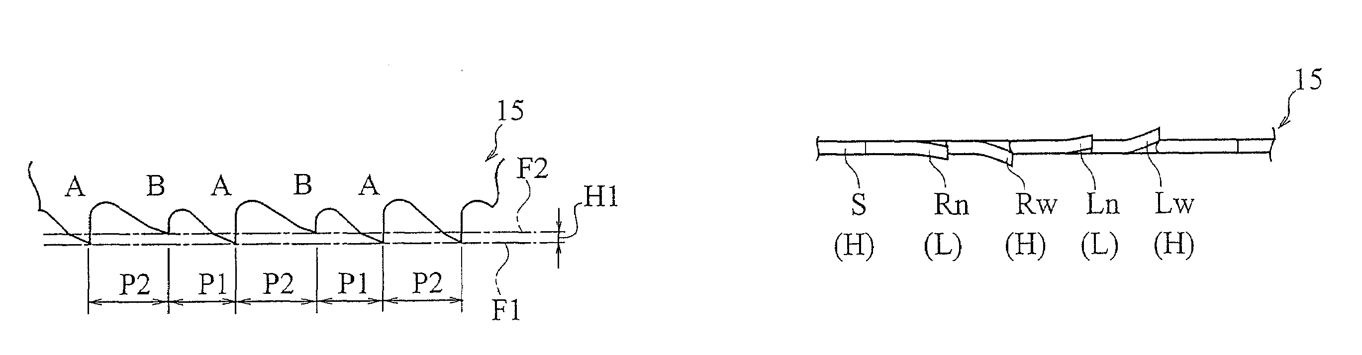
[0082]FIGS. 7A and 7B show a saw blade 3 of the invention. In the saw blade 3, there is a height difference H1 between saw teeth corresponding to the first teeth group A and saw teeth corresponding to the second teeth group B, and distances between the saw teeth are equal pitches P1.

[0083]In other words, the tips of the spur teeth S, Lw and Rw are arranged such as to coincide with a first phantom line F1 shown with chain line. On the other hand, the tips of the saw teeth St, Ln and Rn are arranged such as to coincide with a second phantom line F2 shown with chain line. A height difference between the first phantom line F1 and the second phantom line F2 corresponds to the height difference H1 of the tooth height of the saw teeth.

[0084]Since there is the height difference H1 between the tips of the set teeth S, Lw and Rw and the tips of the saw teeth St, Ln and Rn, depths of garrets thereof are different. That is, the set teeth Ln and Rn belonging to the second teeth group B have low ...

fifth embodiment

[0106]In the saw blade 9 of the fifth embodiment, the arrangement of the left and right set teeth Lw and Rw of the first teeth group A and the left and right set teeth Ln and Rn of the second teeth group B can appropriately be changed. In this case, the left and right set teeth Lw and Rw of the first teeth group A and the left and right set teeth Ln and Rn of the second teeth group B are arranged such that the teeth set in the same direction are not continuously arranged.

[0107]Referring to FIGS. 11A and 11B, in a saw blade 11 of a sixth embodiment of the invention, left and right set teeth Ln2 and Rn2 having low tooth height and small set amount are added to the second teeth group B of the saw blade 5 of the third embodiment shown in FIGS. 8A and 8B, and the number of saw teeth is increased, and the pitches P1 between the saw teeth are equal to each other.

[0108]More specifically, the first teeth group A comprises a total of three teeth, i.e., one spur tooth S having high tooth heigh...


PUM

PropertyMeasurementUnit
Heightaaaaaaaaaa
Heightaaaaaaaaaa

Abstract

A saw blade in which a tooth pattern comprising a first teeth group A and a second teeth group B each having a plurality of set teeth is repeated, wherein the saw blade has at least one or both of the following conditions: a condition in which a tooth height of the second teeth group B is lower than that of the first teeth group A, and a condition in which a set amount of the second teeth group B is smaller than that of the first teeth group A, and wherein the first teeth group A has at least one spur tooth.

Description

TECHNICAL FIELD[0001]The present invention relates to a saw blade such as a band saw, a hacksaw, a circular saw and the like that is a tool for cutting a material to be cut (workpiece) in cutting operation.BACKGROUND TECHNIQUE[0002]A band mill is conventionally used as an apparatus for cutting a large metal workpiece. In a band saw blade used for the band mill, in order to cope with chatter vibration or noise, a pattern of set teeth is set to various set patterns such as raker set, wave set and straight set, and pitch between the teeth is made non-uniform. In order to cope with difficult-to-machine material such as stainless steel, there is developed a saw blade in which a plurality of teeth of the saw blade are varied in height or the set amount of the plurality of set teeth is varied.[0003]To meet commercial requirements, there have been developed various saw blades such as a saw blade in which angles of tips of saw teeth are variously changed, a back surface of the saw blade is c...

Claims


Application Information

Patent Timeline
IPC IPC(8): B27B33/02B23D61/02B23D61/12B23D61/00
CPCB23D61/121B23D61/021Y10T83/9346Y10T83/9348Y10T83/935Y10T83/9353Y10T83/9358B23D61/12
Inventor TSUJIMOTO, SUSUMU
Owner AMADA CO LTD
Why Eureka
Try Eureka