[0006]In the case of an insertion instrument for a multi-part intervertebral endoprosthesis, in particular a cervical
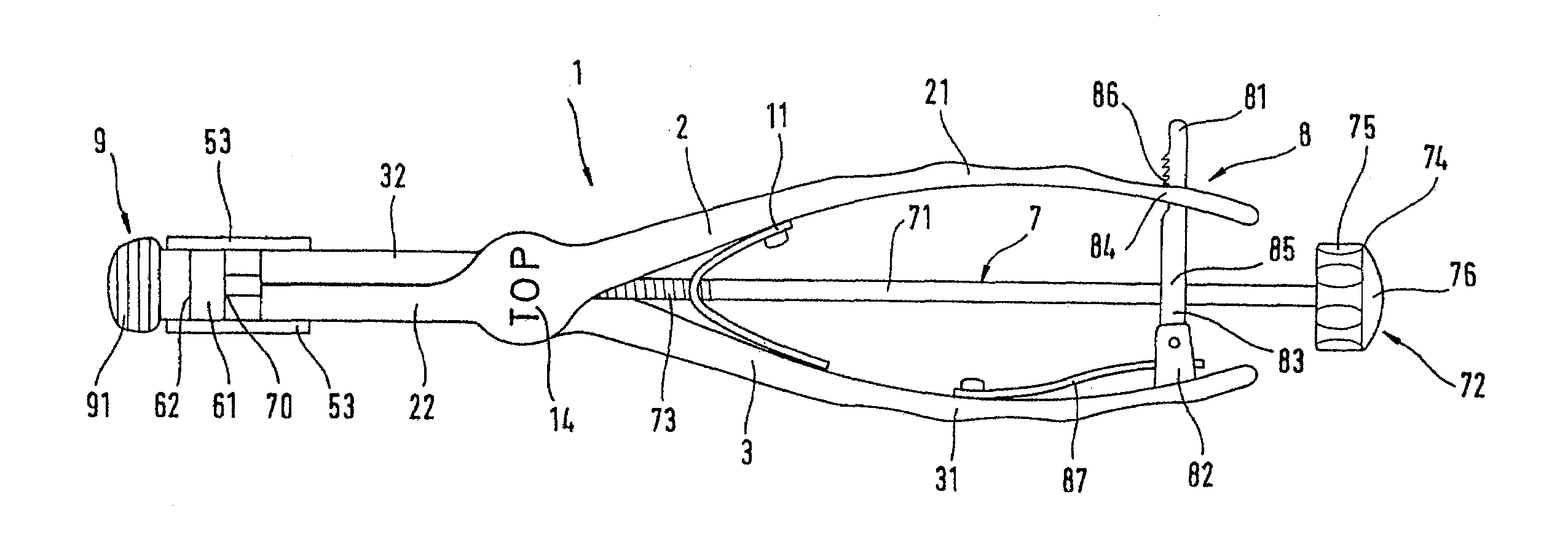
prosthesis, which comprises two closure plates and a sliding core arranged between these, said insertion instrument having a handgrip part, gripping members which hold the closure plates between them, and a force-receiving part for applying an insertion force to the intervertebral endoprosthesis, the invention provides that the gripping members are guided movably toward and away from one another via a hinge and are able to be tensioned against the intervertebral endoprosthesis, projections pointing in the tensioning direction or recesses for holding the intervertebral endoprosthesis with a form-fit are formed on the gripping members, and a block guided in the longitudinal axis direction and with an
abutment surface is provided which can be moved to the intervertebral endoprosthesis by means of an actuating device and, in its forward position, secures the intervertebral endoprosthesis against the projections or recesses. When the
forceps-like insertion instrument is closed, the gripping members connected to one another via a hinge move toward one another and engage with a form-fit via their projections (or recesses) in corresponding depressions (or elevations) of the intervertebral endoprosthesis and thus tension the latter in a direction transverse to the longitudinal axis of the insertion instrument. The longitudinally movably guided block can be moved toward the intervertebral endoprosthesis until its
abutment surface bears on the intervertebral endoprosthesis and secures the latter against the projections (or recesses). In this way, the intervertebral endoprosthesis is also tensioned in the longitudinal direction. It is thus held by the insertion instrument in a manner free of play and in a precise position. By virtue of the block bearing firmly on the intervertebral endoprosthesis, considerable forces, such as arise when striking the intervertebral endoprosthesis into place, can also be safely transmitted. Since these considerable forces are transmitted via the block and its abutment surface, the projections (or recesses) do not have to take up these forces. They can be of fairly small dimension and therefore made very fine, as is desired for precise positioning, without having to take into consideration the high force transmission when striking the intervertebral endoprosthesis home. In addition, by bearing on the intervertebral endoprosthesis, the block ensures that the latter does not inadvertently turn and that its individual elements do not open. By virtue of the invention, the intervertebral endoprosthesis can thus be held easily, safely and with precise positioning on the insertion instrument and inserted.
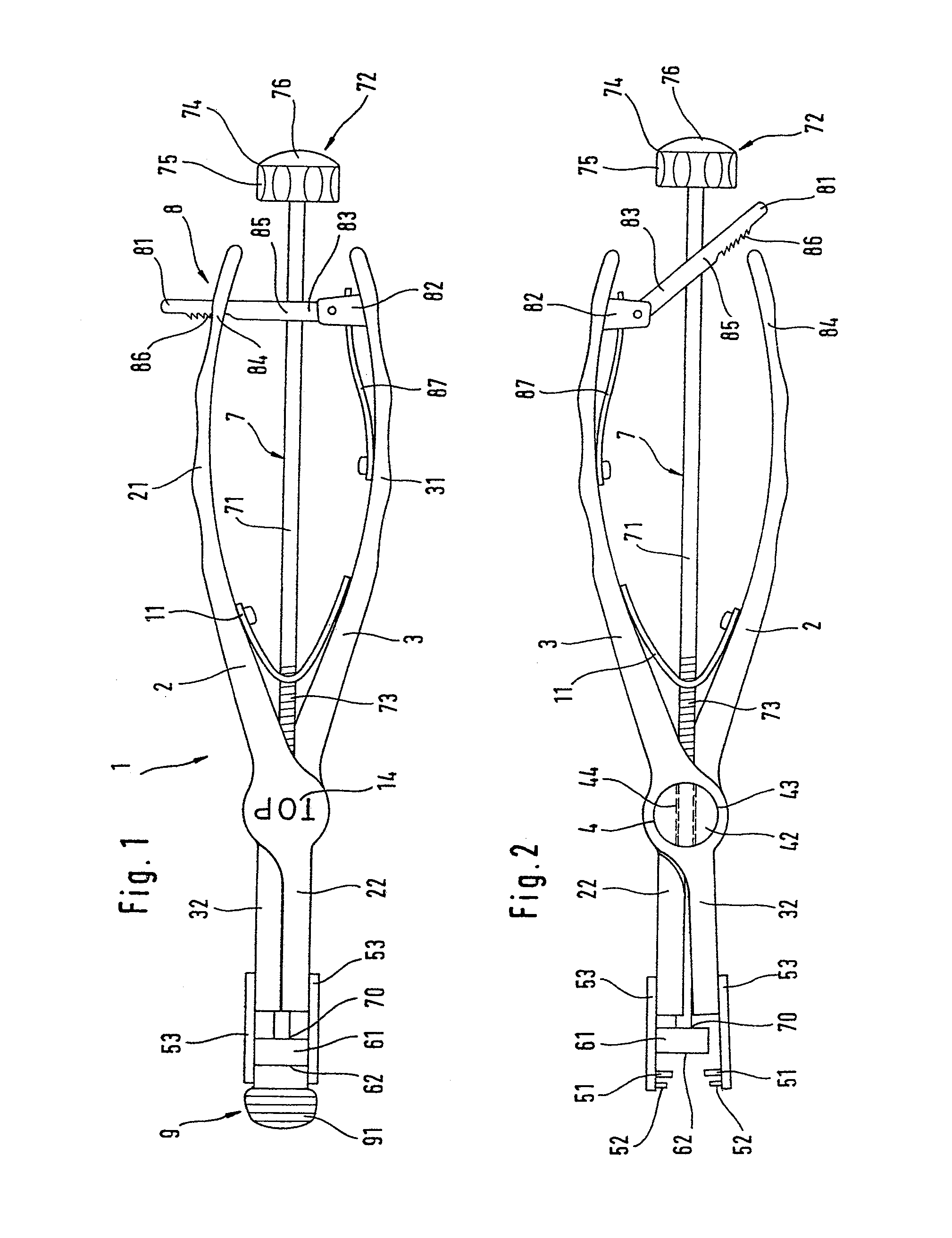
[0011]The insertion instrument is preferably designed as a
forceps, whose jaw parts form the gripping members. This permits a space-saving construction and easy handling, which is of
advantage particularly in the confined conditions in the area of the
cervical spine.
[0012]To make it simpler to use, the actuating device has a rod with a
handle arranged in the rear area of the handgrip part. This allows the operating surgeon to use the actuating device without awkward maneuvering. Because of the small space available in the case of cervical prostheses, this is of particular importance when removing the insertion instrument after introduction of the intervertebral endoprosthesis, when the block has to be moved back. For this purpose, the rod is expediently provided with a
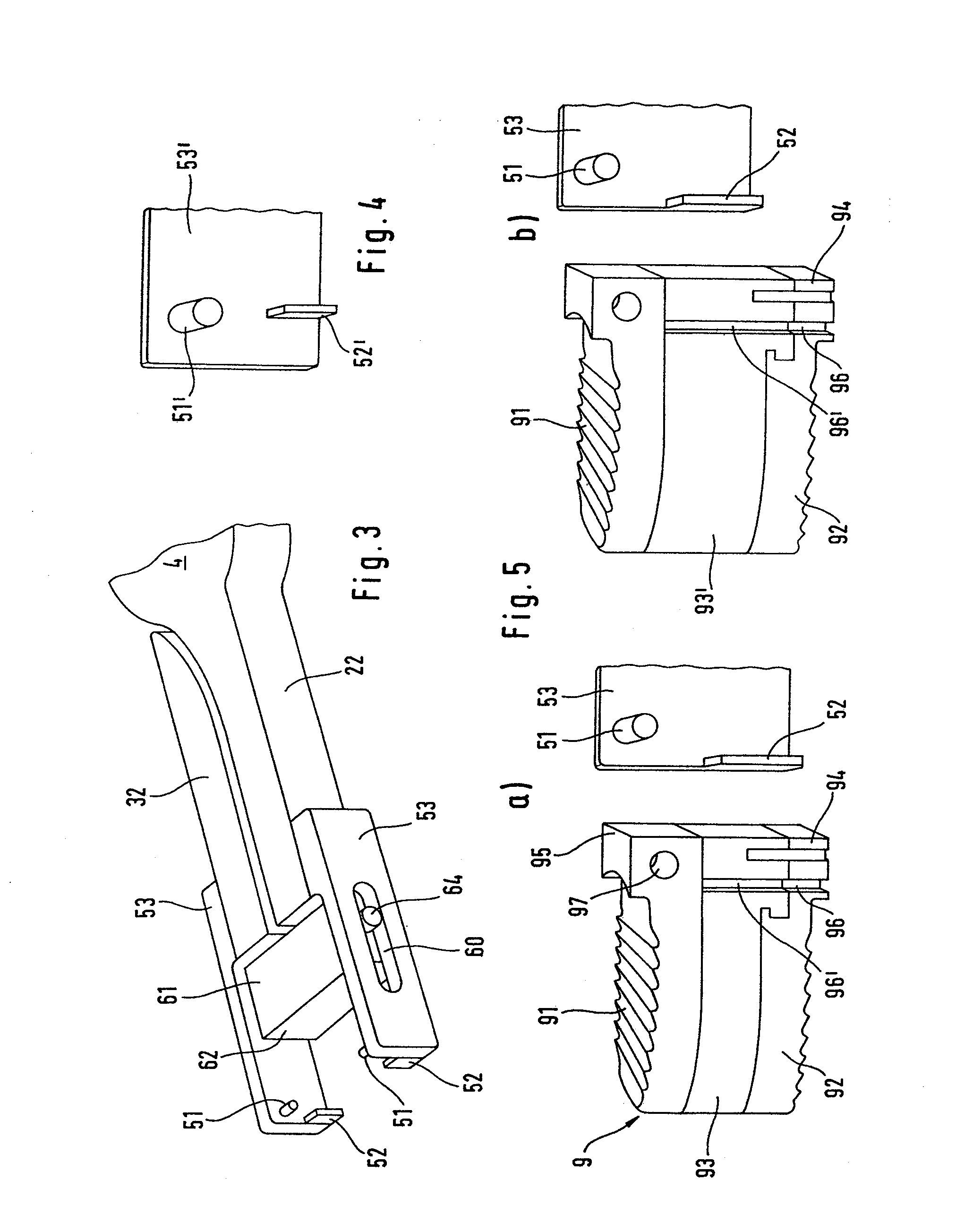
screw thread and is guided in a counterthread which is fixed on the instrument and arranged preferably in the hinge. Thus, by turning in one direction, the block can be guided toward the intervertebral endoprosthesis and thus secure it, whereas, by turning in the opposite direction, the block is moved away and releases the intervertebral endoprosthesis for the purpose of removal of the insertion instrument. The screw device also has the
advantage of being self-locking, with the result that a separate securing device for protection against inadvertent displacement is not necessary. However, a screw device is not absolutely necessary, and, instead, other preferably self-locking actuating devices can also be provided.
[0013]In a particularly advantageous construction, the actuating device is guided through the hinge. This is not only a particularly space-saving design, it also guarantees a near-center arrangement. This arrangement ensures that the insertion instrument does not deviate to the side even under high forces when struck. A high degree of positioning precision when inserting the intervertebral endoprosthesis is achieved in this way.
[0014]It is expedient for the actuating device to have a strike head at its handgrip end. In this way, via the actuating device and the block, it is possible to act directly on the intervertebral endoprosthesis so as to bring it to its
implantation site. For this purpose, it is expedient for the
handle itself to be designed as a strike head. This permits a space-saving construction, which is of considerable value particularly in the confined conditions in the area of the cervical spine.
[0015]In order to ensure that the insertion instrument does not inadvertently spring open, even when acted upon by considerable force, a locking device is expediently provided for securing the handgrip parts in the position when pressed together, said locking device having a guide for the actuating device. This ensures that the actuating device does not deflect outward under high loads, particularly when the strike head is arranged far to the rear. The locking device can be provided at the rear end of the handgrip parts in a manner known per se. It is important that it is sufficiently strongly dimensioned to withstand the loads which occur during striking but can nevertheless be easily released for removing the instrument.

