Conditional battery charging system

a charging system and battery technology, applied in the field of batteries, can solve the problems of increasing internal resistance, reducing battery life, and reducing battery life, so as to enhance the battery life and increase the battery li

Active Publication Date: 2009-08-04
ATREUS LABS LLC
View PDF5 Cites 91 Cited by
  • Summary
  • Abstract
  • Description
  • Claims
  • Application Information

AI Technical Summary

Benefits of technology

[0006]A method and system are provided in which a charging process for rechargeable batteries is controlled in accordance with selected predetermined variable conditions. In order to increase battery life span, the charging of a rechargeable battery is selectively suspended prior to a fully charged state depending upon the current status of the predetermined variable conditions. In an exemplary embodiment, a user is enabled to select the predetermined conditions under which the charging of a battery is suspended until such conditions have changed. Such conditions include, for example, physical location of the battery being charged and / or the time and / or date when the battery is being charged. A user GUI is provided to enable a user to input selected times and / or dates and / or locations when the device containing the battery is likely to be away from a charging source and needs to be fully charged, and / or selected times and / or dates and / or locations when the device is likely to have access to a power source and the battery is enabled to be charged only to a storage level, short of a full charge, in order to enhance the lifespan of the battery.

Problems solved by technology

Batteries using such technologies typically last between two and three years during which they continually lose capacity to hold a charge for long enough periods of time.
The capacity loss manifests itself in increased internal resistance caused by oxidation.
Eventually, the cell resistance reaches a point where the battery pack can no longer deliver the stored energy although the battery may still show as being fully charged.
However, most users are unwilling to do so because of fear of loss of data if the operation of the AC-DC adapter is interrupted in any way.

Method used


Image

  • Conditional battery charging system
  • Conditional battery charging system
  • Conditional battery charging system

Examples


Embodiment Construction

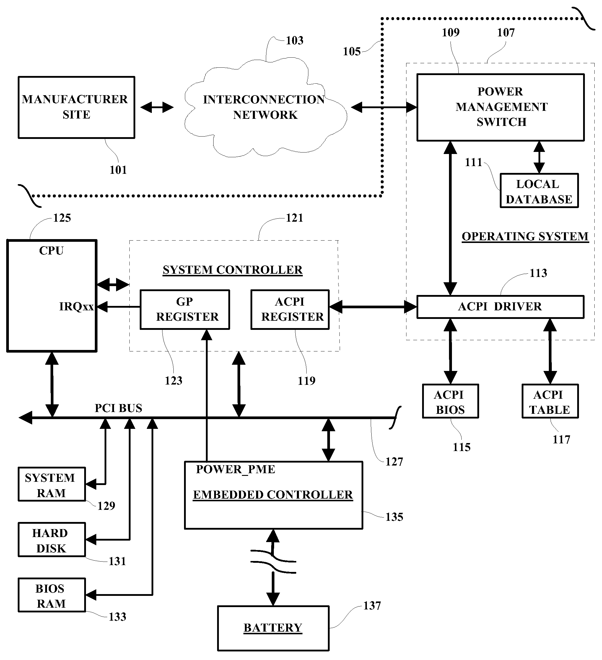
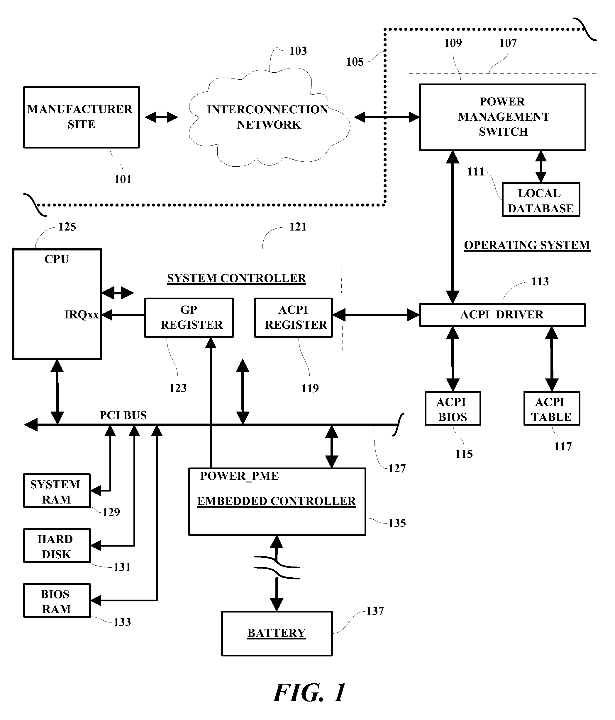
[0013]It is noted that devices which are shown in block or schematic form in the drawings are generally known to those skilled in the art, and are not specified to any greater extent than that considered necessary as illustrated, for the understanding and appreciation of the underlying concepts of the present invention and in order not to obfuscate or distract from the teachings of the present invention. Also, as used herein, the terms “inactive status” and “storage status” for rechargeable batteries have the same meaning and are used interchangeably.

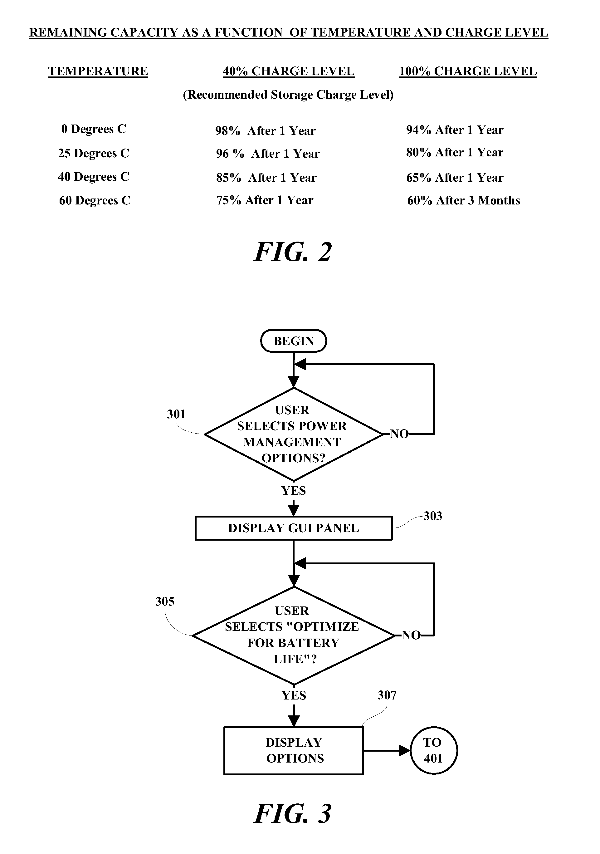
[0014]The process described herein includes several battery life enhancement features. For example, in a system for charging the battery within a notebook computer, the system is selectively programmed to connect to and interrogate the battery manufacturer. The system determines the Model and type information from the notebook and automatically contacts the manufacturer's online database to download the latest optimal charging threshold...


PUM

PropertyMeasurementUnit
chargeaaaaaaaaaa
storage chargeaaaaaaaaaa
time periodaaaaaaaaaa

Abstract

A method and system are provided in which a charging process for rechargeable batteries is controlled in accordance with selected predetermined variable conditions. In an exemplary embodiment, a user is enabled to select the predetermined conditions under which the charging of a battery is suspended until such conditions have changed. Such conditions include, for example, physical location of the battery being charged and / or the time and / or date when the battery is being charged. A user GUI is provided to enable a user to input selected times and / or dates and / or locations when the device containing the battery is likely to be away from a charging source and needs to be fully charged, and / or selected times and / or dates and / or locations when the device is likely to have access to a power source and the battery is enabled to be charged only to a storage level.

Description

RELATED APPLICATIONS[0001]Subject matter disclosed and not claimed herein is disclosed and claimed in related co-pending application, Ser. No. 11 / 684,018, which is assigned to the assignee of the present application.FIELD OF THE INVENTION[0002]The present invention relates generally to battery charging systems and more particularly to a system and methodology for enabling optimization of battery life for rechargeable batteries.BACKGROUND OF THE INVENTION[0003]An important component of mobile computing devices is the battery. Typically Lithium-ion batteries are used in such applications. Batteries using such technologies typically last between two and three years during which they continually lose capacity to hold a charge for long enough periods of time. The capacity loss manifests itself in increased internal resistance caused by oxidation. Eventually, the cell resistance reaches a point where the battery pack can no longer deliver the stored energy although the battery may still s...

Claims


Application Information

Patent Timeline
Patent Type & Authority Patents(United States)
IPC IPC(8): H01M10/44H01M10/46
CPCH02J7/0075H02J7/0069
Inventor BANSAL, RAVI PRAKASHHAMILTON, II, RICK ALLENO'CONNELL, BRIAN MARSHALLWALKER, KEITH RAYMOND
Owner ATREUS LABS LLC
Why Eureka
Try Eureka