Method and apparatus for displaying images with compression mechanism

a compression mechanism and image technology, applied in the field of apparatus for displaying images, can solve the problems of reducing the compression rate, so as to achieve the effect of pulling back the compression rate and increasing the compression ra

Active Publication Date: 2009-08-04
TAIWAN IMAGINGTEK
View PDF11 Cites 25 Cited by
  • Summary
  • Abstract
  • Description
  • Claims
  • Application Information

AI Technical Summary

Benefits of technology

[0011]The present invention is related to a method and apparatus of the image buffer compression of the display device, which plays an important role in image data reduction, specifically in compressing the frame buffer image of the display device driver, display device controller and line image buffer within the display device controller. The present invention significantly reduces required storage device density and accessing bandwidth of the image within the storage device.
[0012]The present invention of the image compression compresses the image data of display driver before storing the image data into a frame buffer which significantly reduces the density, bandwidth requirement and power consumption of storage device.
[0027]According to an embodiment of the present invention of the image compression, the distribution of truncating bits will not start from the same position hence avoid accumulation of error over time.
[0030]According to an embodiment of the present invention of the image compression, adaptively change the block size from block to block is applied to achieve higher performance and still maintain high compression rate and good quality.

Problems solved by technology

Because the de-interlacer 124 needs to access reference frames so frequently, the channel between the display control chip 12 and the off-chip memory 16 needs high bandwidth, which consumes higher power and complicates the design of the display system.
The frame buffer is also a cost factor during designing the display system.

Method used


Image

  • Method and apparatus for displaying images with compression mechanism
  • Method and apparatus for displaying images with compression mechanism
  • Method and apparatus for displaying images with compression mechanism

Examples


Embodiment Construction

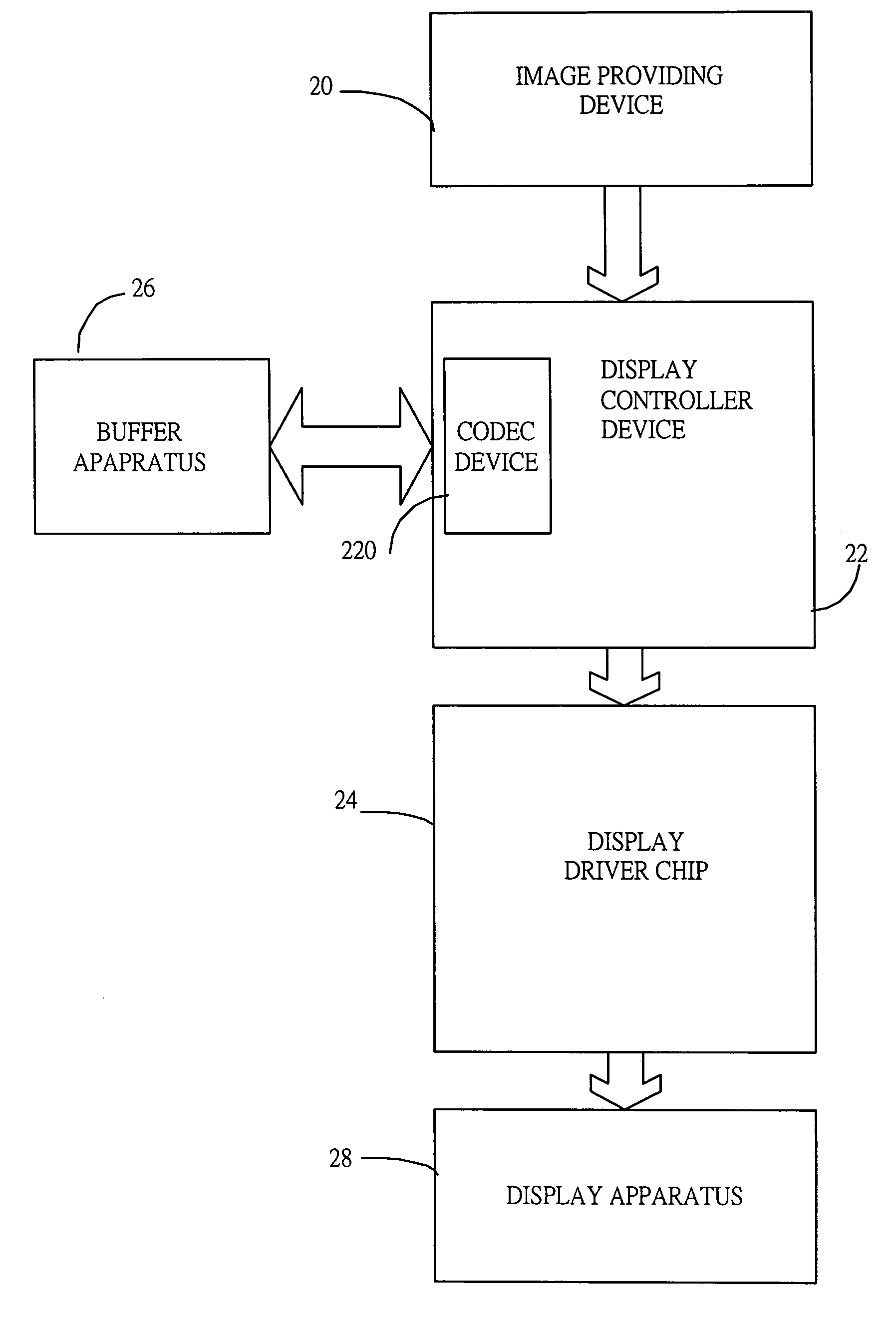
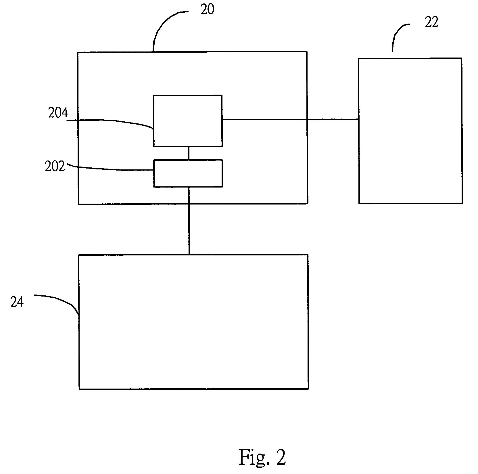
[0054]FIG. 2 is a diagram illustrating a preferred embodiment according to the present invention. A display processing apparatus 20 is designed for adapting one or more raw image(s) for displaying on a display apparatus 22. For example, the raw image(s) comes from a MEPG / JEPG decoder and the display apparatus 22 is a LCD display. The display processing apparatus 22 has a frame codec device 202 for compressing the raw image(s) to generate an associated compressed image to be stored in at least one buffer apparatus 24 that is coupled to the display processing apparatus 22. The display processing apparatus 22 also has one or more manipulating device(s) 204 for generating an output image adapted to be display on the display apparatus according to a decompressed image from the frame codec device 24 by decompressing the compressed image.

[0055]In one exemplary implementation of the preferred embodiment, the display processing apparatus 20 is designed as a chip and the buffer apparatus 24 i...


PUM


Abstract

A codec device is disposed in a display control device for instantly supplying decompressed image data to manipulating devices in the display control chip. Reference images are stored in compressed format after instantly compressed by the codec device. In addition, MSB portions and LSB portions are separately compressed for gaining higher compression ratio. Predication of the pixel value is also modified in variable length coding. On-chip line buffer is also applied with the instant compression mechanism. Fixed compression ratio is predetermined to actually downsize the chip design for the worst case.

Description

BACKGROUND OF THE INVENTION[0001]1. Field of Invention[0002]The present invention relates to apparatus for displaying images, and particularly relates to apparatus for displaying images with compression mechanism.[0003]2. Description of Related Art[0004]With top image quality in display, the LCD, Liquid Crystal Display has become prevailing popular in mass applications including monitor, screen of note book computer, display screen of mobile phone, PDA, GPS, e-dictionary, . . . etc. Digital TV and HDTV are adopting LCD display as its display screen. The digital image and motion video have been adopted in an increasing number of applications, which include digital camera, scanner / printer / fax machine, video telephony, videoconferencing, surveillance system, VCD (Video CD), DVD, digital TV . . . etc. The success of development of the digital image and video compression standards fuels wider applications in digital display devices.[0005]FIG. 1(a) is a diagram of a display system. In the...

Claims


Application Information

Patent Timeline
Patent Type & Authority Patents(United States)
IPC IPC(8): G06K9/36
CPCH04N19/105H04N19/176H04N19/184H04N19/186H04N19/132
Inventor SUNG, CHIH-TA STARLAN, YIN-CHUN
Owner TAIWAN IMAGINGTEK
Why Eureka
Try Eureka