
Method and apparatus of high quality video compression

a video compression and video data technology, applied in the field of video data compression, can solve the problems of loss of image information, slow video compression, and the lossy algorithm's scaling mechanism becoming even more complex in achieving good image quality, so as to reduce the density of the required storage device, the effect of top image quality and good quality

Inactive Publication Date: 2007-04-26
TAIWAN IMAGINGTEK
View PDF38 Cites 44 Cited by
  • Summary
  • Abstract
  • Description
  • Claims
  • Application Information

AI Technical Summary

Benefits of technology

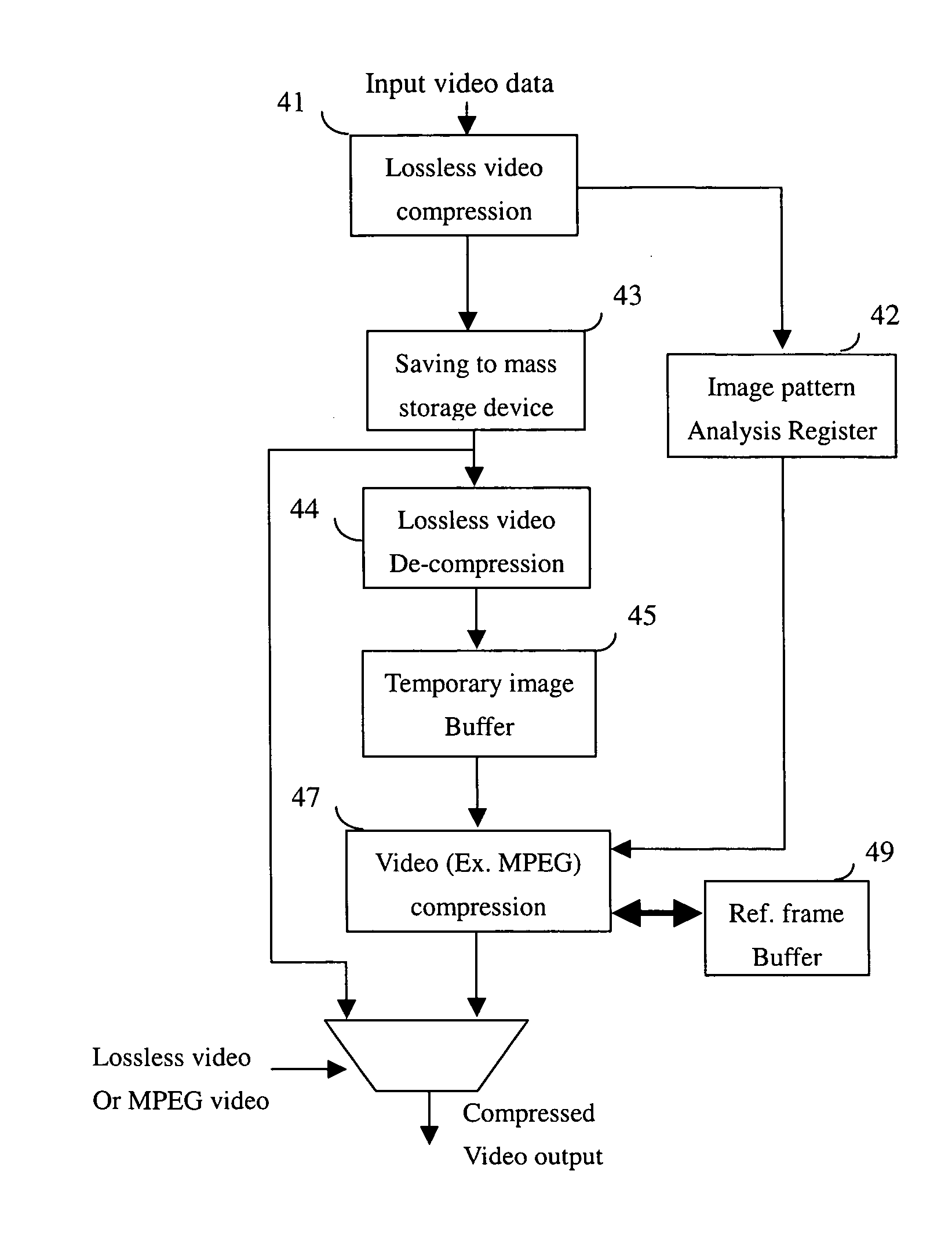
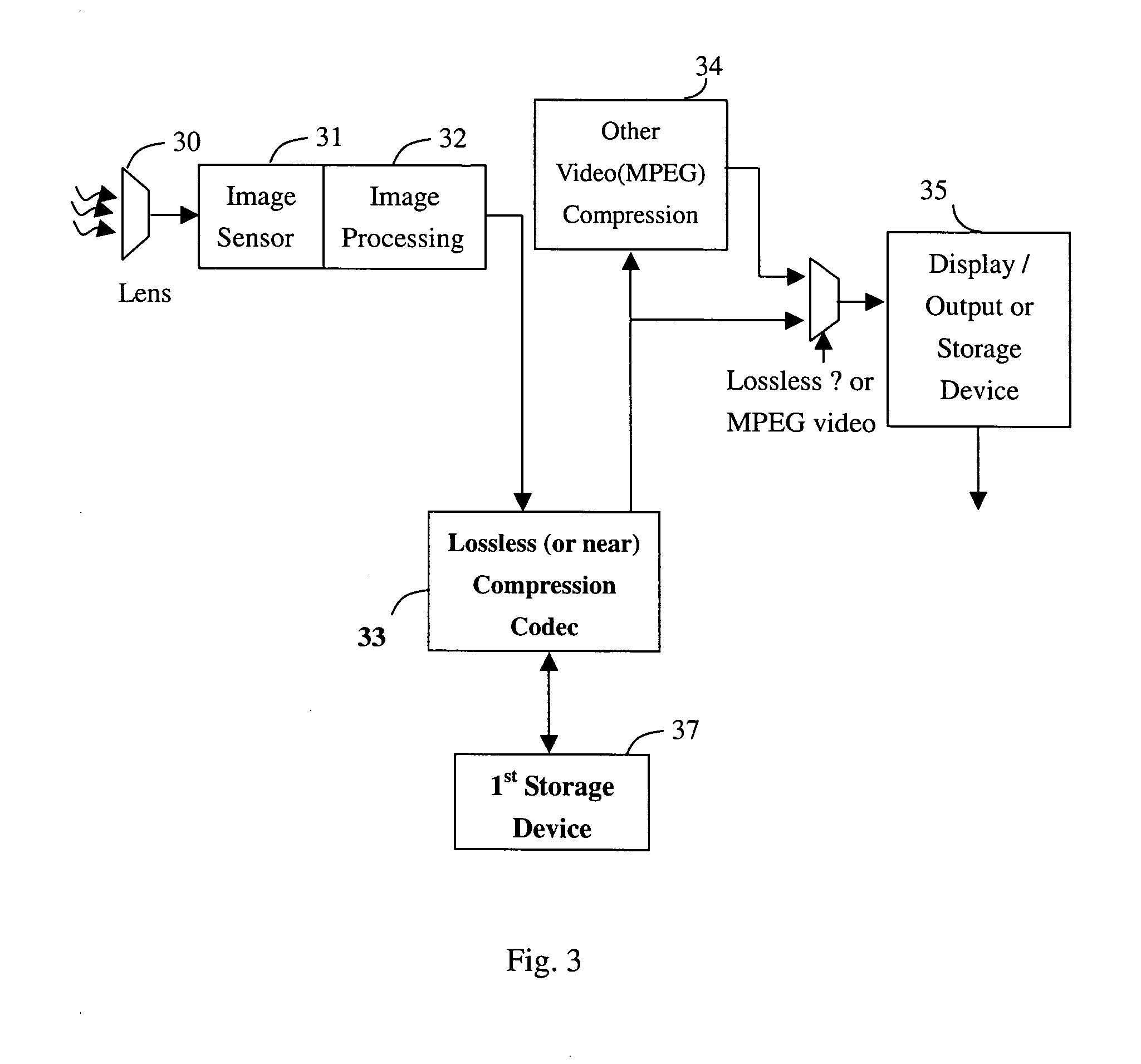
[0008] The present invention is related to an apparatus of video recording and display system, which plays an important role in video data reduction, specifically in compressing the video data before saving it to the storage device and display with top image quality. The present invention significantly reduces the required storage device density and maintains good quality to the original image quality or minimized loss rate of the raw image data if a lossless or near lossless output / display is selected by the user. The present invention of the method of video recording and display system applies a lossless video compression mechanism to significantly reduce the requirement of density, bandwidth and power consumption of the first storage device. The present invention of the apparatus of video recording and display system applies another near lossless video compression mechanism to significantly reduce the density, bandwidth requirement and power consumption of the storage device. According to another embodiment of the present invention, the first compressed video frames are decompressed and re-compress by a second video compression algorithm. According to another embodiment of the present invention, the pattern complexity of each frame of the firstly compressed video stream is used to decide the bit rate of the corresponding frame in the second round of the video compression. According to another embodiment of the present invention, the second round of the video compression is done when the video capturing device is turned off.

Problems solved by technology

The disadvantage of the MPEG video compression technology is the loss of image information since most video compression including MPEG are lossy algorithm which have more or less image data loss to a certain of degree.
When recovering from the compressed video sequence, the video scaling mechanism become even complex in achieving good image quality which most likely needs more frames of previous pictures to predict the missing image lost in video compression procedures.
Procedures of scaling and playback the compressed video data of lossy algorithm including MPEG is very costly, slow and can not recover back to the quality of the original image.
This means the loss of MPEG video causes high cost in de-interlacing during displaying an decompressed MPEG video data.

Method used


Image

  • Method and apparatus of high quality video compression
  • Method and apparatus of high quality video compression
  • Method and apparatus of high quality video compression

Examples


Embodiment Construction

[0021] In the past decades since the new venture of the semiconductor CCD image capturing sensor which provides good quality in capturing picture, some still image and motion video related applications have boomed the market. Even the image quality or so named the “Dynamic range” is still far behind CCD sensor, the CMOS image sensors are invading the image sensor market in the past decade. The applications of the semiconductor image sensor in still image include scanner, digital still camera (DSC), in motion video include video conference, Web (or PC) camera, surveillance system, mobile phone, video recorder . . . In the video recording applications, the most popular products include the camcorder, DSC with motion video capturing function and other video recording devices. In the present invention of the video recording and display system, the apparatus applies to but not limited to above products.

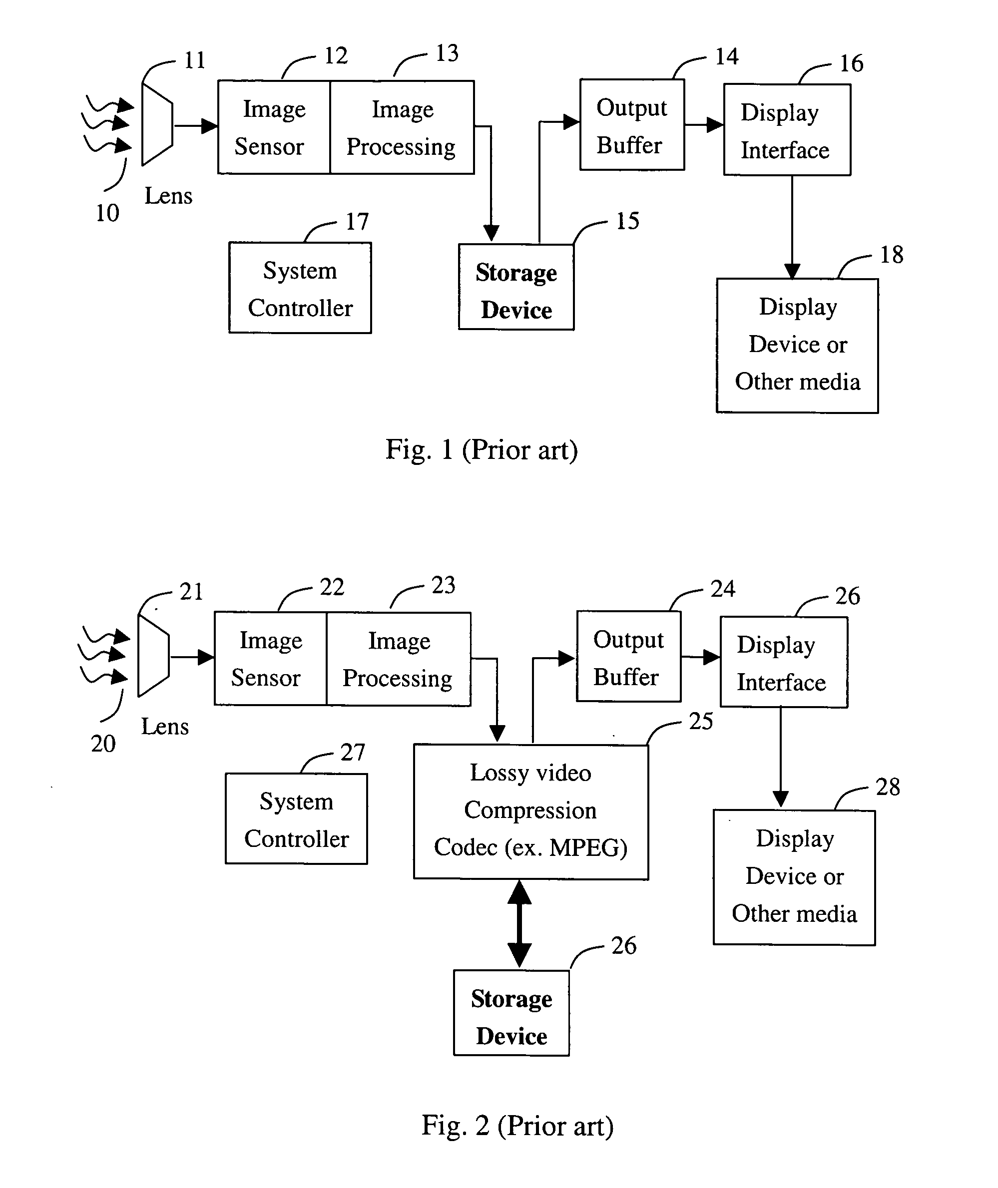
[0022]FIG. 1 illustrates a prior art video recording system without applying image co...


PUM


Abstract

A video compression method compresses the capture video raw data into the 1st compression format and records the image patter complexity of each frame of a predetermined amount of video frames. The information of the image pattern complexity is used to determine the bit rate of each frame for the 2nd time of the video compression. For saving the image buffer size and speeding up the accessing time, a lossless and near lossless video compression algorithm is applied to the 1st video compression algorithm.

Description

BACKGROUND OF THE INVENTION [0001] 1. Field of Invention [0002] The present invention relates to video data compression, and more particularly relates to the video lossless compression and a mechanism of converting the lossless compression video to another lossy video compression format to reduce the data amount while achieving high image quality. [0003] 2. Description of Related Art [0004] With top image quality in capturing, processing and display, the semiconductor image sensor including CCD, the Charge Coupled Device has since late year 1970 become adopted in video recording system as the image capturing device as so named “Camcorder” device for recording motion pictures. Due to the consideration of cost, in the past decades, the captured video data within a recording system have been stored into magnetic tapes. Some popular storage media is the 8 mm magnetic tape which can store up to ˜2 hours of VGA (640×480 pixels) resolution with 30 fps, frame per second resolution video. Th...

Claims


Application Information

Patent Timeline
Patent Type & Authority Applications(United States)
IPC IPC(8): G06K9/36
CPCH04N19/159H04N19/15H04N19/12H04N19/61H04N19/115
Inventor SUNG, CHIH-TA STAR
Owner TAIWAN IMAGINGTEK
Learn More