Methods and algorithms for joint channel-code decoding of linear block codes

a linear block code and channel-code technology, applied in the field of joint channel-code detectors, can solve the problems of insufficient error correction capability of linear block code, poor performance of such a detector b>10/b>, and complicated detection, etc., to achieve the effect of facilitating pp implementation

Active Publication Date: 2009-08-04
MARVELL ASIA PTE LTD
View PDF15 Cites 54 Cited by
  • Summary
  • Abstract
  • Description
  • Claims
  • Application Information

AI Technical Summary

Benefits of technology

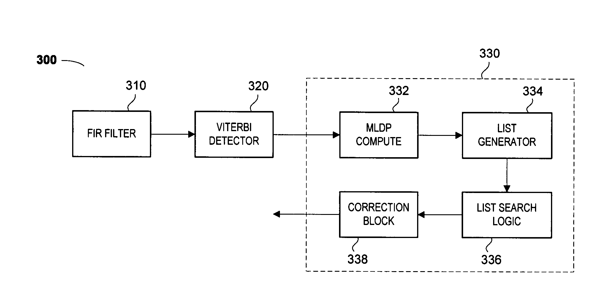
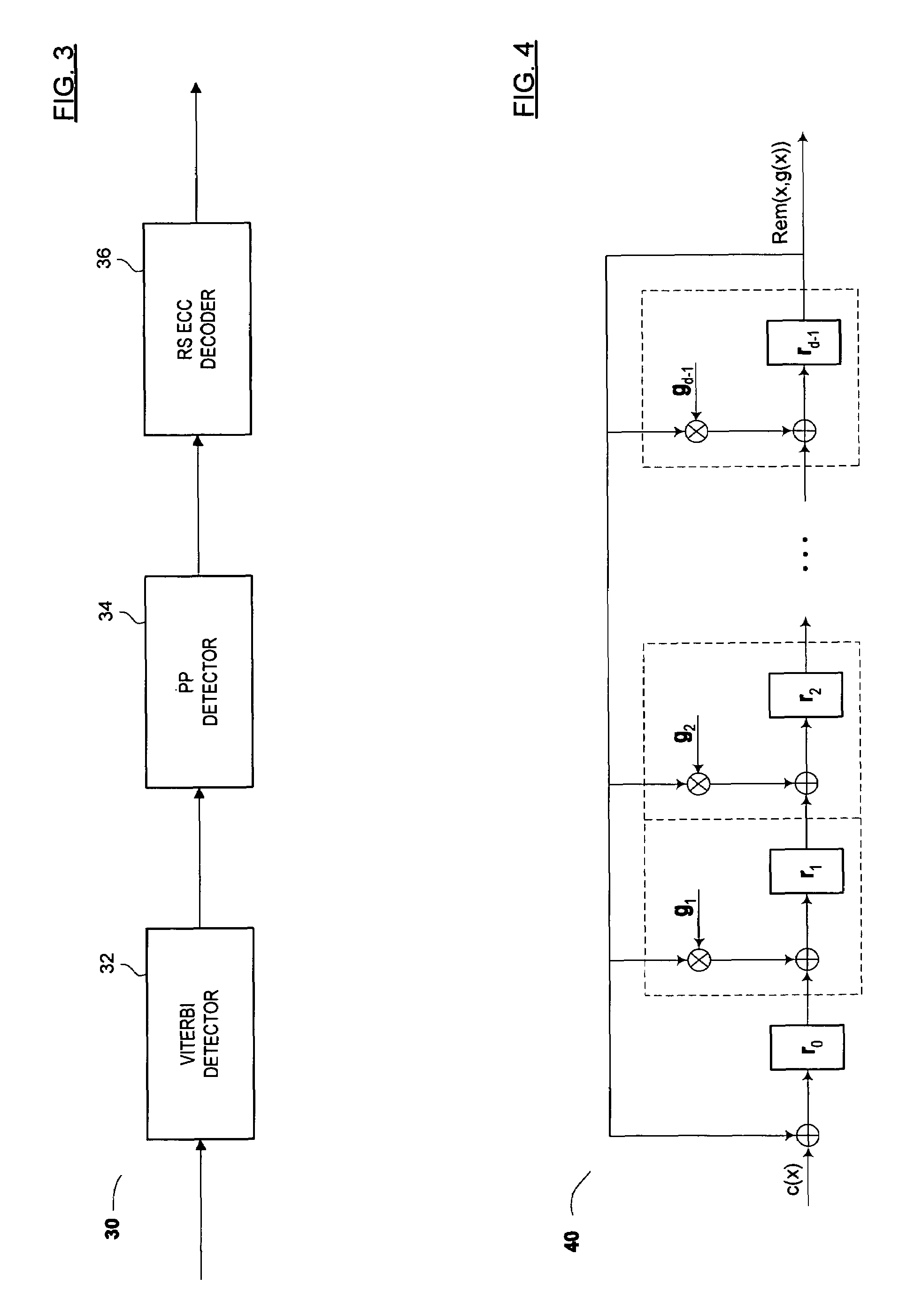
[0037]The present invention focuses on the joint channel-code decoding of inner CRC, generally implemented in a post processor or circuit including a post processor. Thus, the present invention concerns, in one important aspect, a detector implementation for performing steps 3 and 4 listed below paragraph [0018] above, described with reference to a PP decoding architecture. The outer RS ECC decoder may be separated from inner CRC decoding circuitry, as discussed above. The new architecture facilitates PP implementation for codes with large block length and allows parameter N to be set as high as deg(g(x)). For instance, the present PP design can easily support (1023, 1012) CRC codes with g(x)=1+x+x7+x8+0+x10+x11, where n=deg(g(x))=11, or (4096+43, 4096) code where n=deg(g(x))=43.

Problems solved by technology

However, these detectors tend to be very complicated, even for relatively simple (and ultimately weak) codes.
Nevertheless, the performance of such a detector 10 is much worse compared to what can be achieved by joint ML channel-code decoders.
In some instances, the error correction capability of linear block code might not be sufficient to meet the demands of certain applications.
Of course, more error events can be added to the list, but there is a very practical trade-off between performance (e.g., processing speed) and complexity (e.g., number of error events in E).
Secondly, PP-based approaches generally assume that there are at most M errors per CRC codeword.
These assumptions may lead to performance degradation.
For instance, if the true error event corrupting some CRC codeword is not an element of E, or if there is a composite error event consisting of more than M (e.g., some combination of two or more events within E), PP architectures are generally not going to be able to find the transmitted codeword.
To make things worse, a PP architecture may converge to an incorrect CRC codeword (e.g., a codeword other than the one that was transmitted) or erroneously correct the CRC codeword, which may actually increase the number of errors present in the CRC codeword following Viterbi detection.
The codes described above have very small minimum distances, and as a result, are not very good at error correction.
For instance, SPC code has dmin=2, and as a result, it is unable to correct a single error.
Consequently, MLDP for overlapped error events are difficult to calculate.
Therefore, even if such error events are selected by a PP algorithm, they should be disabled in the correction block if their MLDP can not be accurately calculated.
However, even for relatively small values of N, the number of paths to be considered in step 4 can be very large.
In the past, the choice of CRC codes which can be implemented in practice were limited to codes having relatively small block length n (generally, under 120 bits), due to the complexity of having to search through a large number of paths.
However, as previously discussed, the complexity of a PP-based architecture is ultimately related to the choice of parameter M. On the other hand, short CRC codes are not optimal either due to (i) the relatively low error detection and correction capability of these codes and / or (ii) the high code rate penalty they inflict on the communication system.
However, if such a non-trivial candidate path is not identified, then the received code word is not corrected and decoding failure is declared (see result 84).

Method used


Image

  • Methods and algorithms for joint channel-code decoding of linear block codes
  • Methods and algorithms for joint channel-code decoding of linear block codes
  • Methods and algorithms for joint channel-code decoding of linear block codes

Examples


Embodiment Construction

[0051]Reference will now be made in detail to the preferred embodiments of the invention, examples of which are illustrated in the accompanying drawings. While the invention will be described in conjunction with the preferred embodiments, it will be understood that they are not intended to limit the invention to these embodiments. On the contrary, the invention is intended to cover alternatives, modifications and equivalents that may be included within the spirit and scope of the invention as defined by the appended claims. Furthermore, in the following detailed description of the present invention, numerous specific details are set forth in order to provide a thorough understanding of the present invention. However, it will be readily apparent to one skilled in the art that the present invention may be practiced without these specific details. In other instances, well-known methods, procedures, components, and circuits have not been described in detail so as not to unnecessarily ob...


PUM

PropertyMeasurementUnit
threshold numberaaaaaaaaaa
run lengthaaaaaaaaaa
distanceaaaaaaaaaa

Abstract

Circuits, architectures, methods and algorithms for joint channel-code decoding of linear block codes, and more particularly, for identifying and correcting one or more errors in a code word and / or for encoding CRC (or parity) information. In one aspect, the invention focuses on use of (i) remainders, syndromes or other polynomials and (ii) Gaussian elimination to determine and correct errors. Although this approach may be suboptimal, the present error checking and / or detection scheme involves simpler computations and / or manipulations than conventional schemes, and is generally easier to implement logically. Since the complexity of parity-based error correction schemes increases disproportionately to the number of potential error events, the present invention meets a long-felt need for a scheme to manage error detection and / or correction in systems (such as magnetic recording applications) where there may be a relatively large number of likely error events, thereby advantageously improving reliability and / or performance in channel communications.

Description

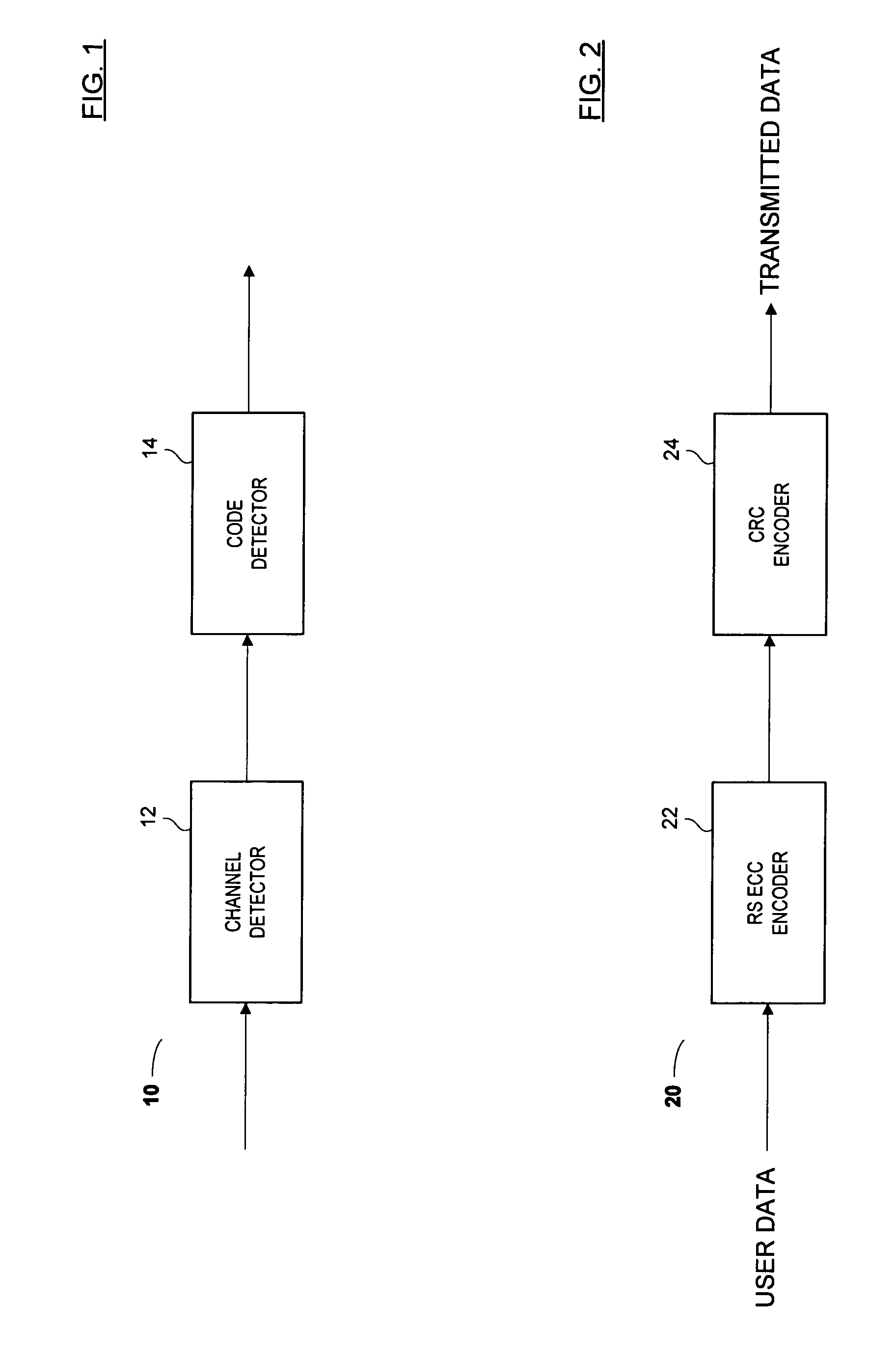
FIELD OF THE INVENTION[0001]The present invention relates generally to joint channel-code detectors. More particularly, the present invention relates to the design and (hardware) implementation of joint channel-code detectors for linear block codes. Although the discussion of the present invention herein below shall primarily refer to applications to magnetic recording channels, the approaches discussed herein can easily be adapted to many other communication channels.DISCUSSION OF THE BACKGROUND[0002]For some linear block codes, one may design a joint Maximum Likelihood (ML) channel-code detector. However, these detectors tend to be very complicated, even for relatively simple (and ultimately weak) codes. In some special cases, one may obtain reasonable performance by completely separating the channel detector 12 from the code decoder 14, as shown in the system 10 in FIG. 1.[0003]A system such as that shown in FIG. 1 could use, for example, Reed-Solomon (RS) Error Correction Code (...

Claims


Application Information

Patent Timeline
Patent Type & Authority Patents(United States)
IPC IPC(8): G11B20/18H03M13/05
CPCG11B20/1833G11B2020/1836G11B2020/1843G11B2220/2516G11B2020/1859G11B2020/1863G11B2020/1853
Inventor BURD, GREGORYWU, ZINING
Owner MARVELL ASIA PTE LTD
Why Eureka
Try Eureka