
Voltage detection device and electric vehicle including voltage detection device

a voltage detection device and voltage detection technology, applied in electric devices, battery/fuel cell control arrangements, instruments, etc., can solve the problems of inaccurate correction of detection errors, the inability of battery voltage detection devices to generate internal reference voltages greater than the reference voltage, etc., to achieve accurate correction of detection errors

Inactive Publication Date: 2009-08-11
PANASONIC EV ENERGY CO LTD
View PDF4 Cites 26 Cited by
  • Summary
  • Abstract
  • Description
  • Claims
  • Application Information

AI Technical Summary

Benefits of technology

The present invention provides a voltage detection device that can accurately correct detection errors in voltages greater than or equal to an internal reference voltage. This device can be used in electric vehicles and includes a first switch group, a charge-discharge unit, and a voltage detector. The first switch group obtains the voltage across one of a plurality of battery blocks, each containing rechargeable batteries. The charge-discharge unit includes two or more capacitors that are charged with the voltage across the battery block or a predetermined internal reference voltage. The voltage detector receives a discharge voltage from the capacitors and detects it. The detection error of the voltage detector is corrected using the discharge voltage of the capacitors as a reference. This device helps to ensure accurate voltage detection in electric vehicles and other applications.

Problems solved by technology

However, the battery voltage detection device cannot generate an internal reference voltage that is greater than or equal to the step down voltage of the zener diode, which functions as the constant voltage step-down circuit.
Therefore, when detecting a relatively high battery block voltage with the battery voltage detection device of the prior art, detection errors cannot be accurately corrected.

Method used


Image

  • Voltage detection device and electric vehicle including voltage detection device
  • Voltage detection device and electric vehicle including voltage detection device
  • Voltage detection device and electric vehicle including voltage detection device

Examples


Embodiment Construction

[0015]In the drawings, like elements are used for like elements throughout.

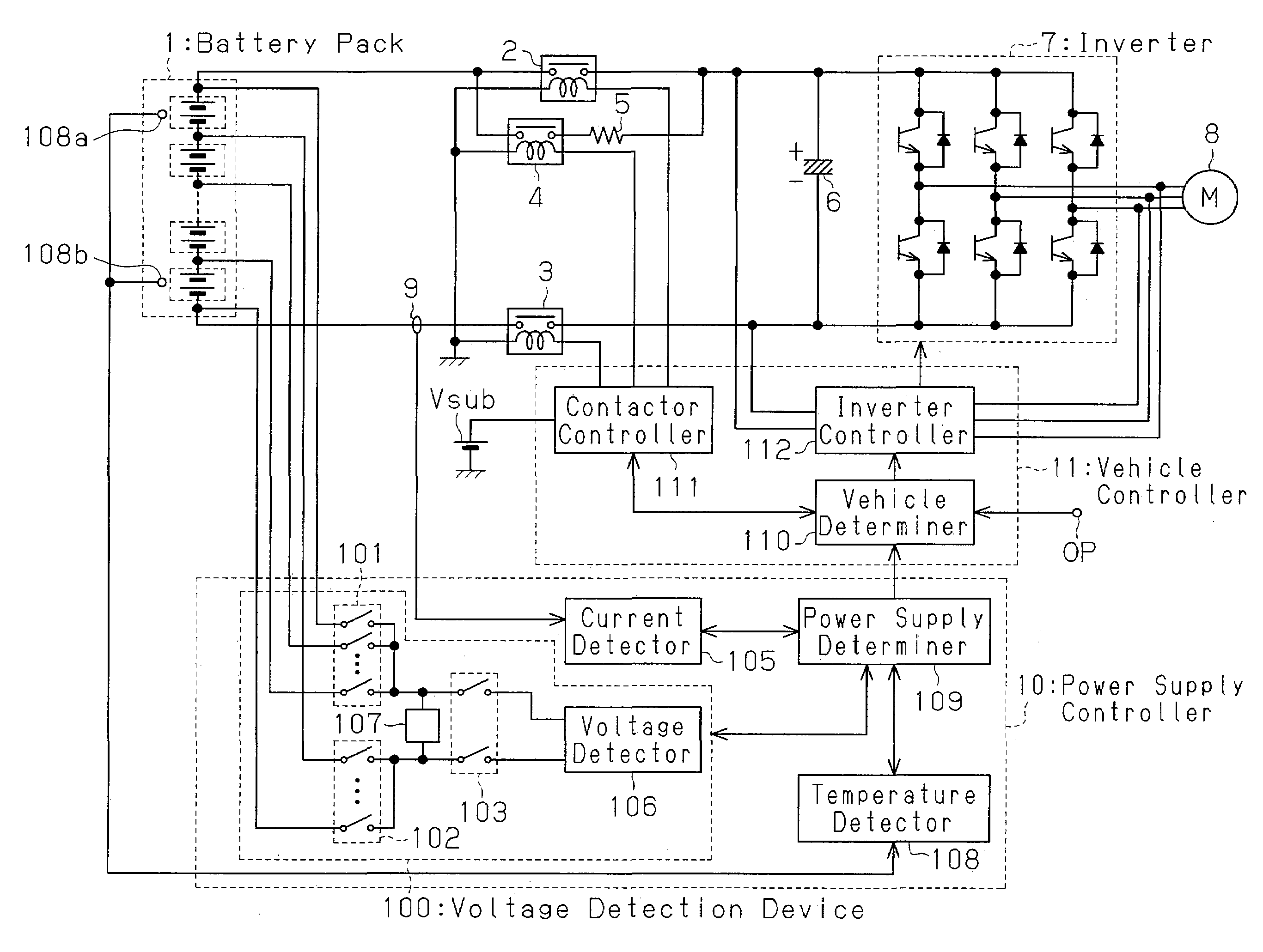
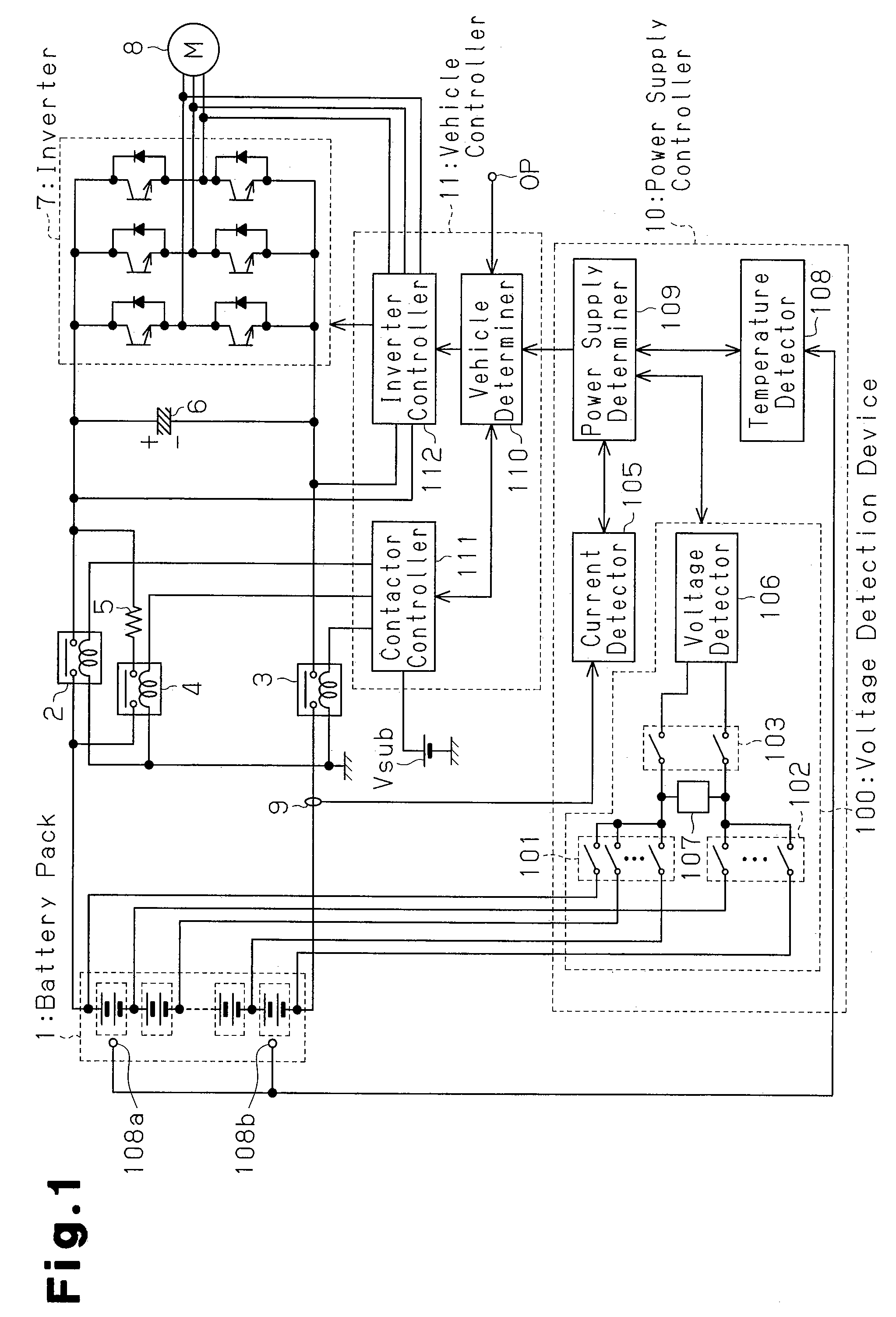
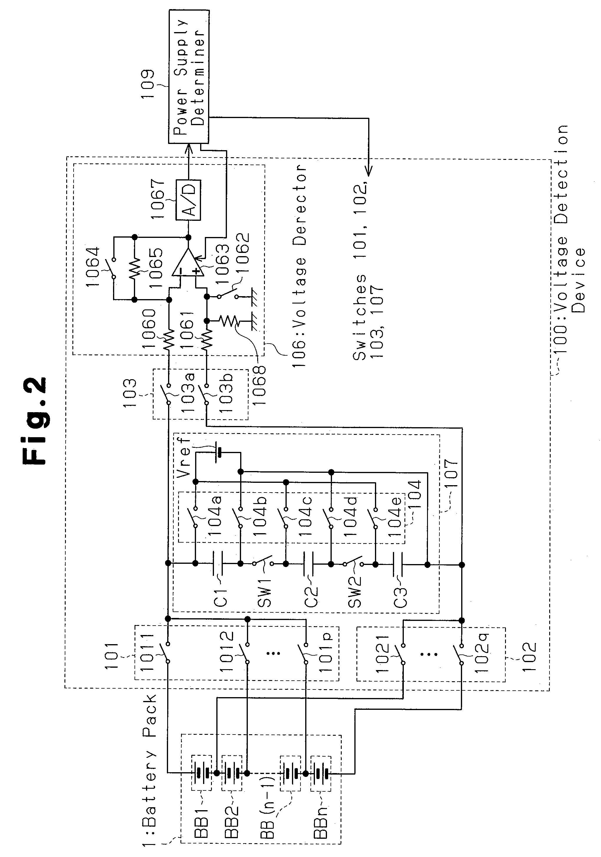
[0016]A voltage detection device 100 according to a preferred embodiment of the present invention will now be described with reference to FIGS. 1, 2, and 3. FIG. 1 is a block diagram showing the structure of an electric vehicle incorporating the voltage detection device 100 of the preferred embodiment. As shown in FIG. 1, the electric vehicle includes a battery pack 1, a high side contactor 2, a low side contactor 3, a precharge contactor 4, a limiting resistor 5, a capacitor 6, an inverter 7, a motor generator 8, a current sensor 9, a power supply controller 10, and a vehicle controller 11.

[0017]The battery pack 1, which is formed by a plurality of series-connected battery blocks, is a power supply having a total voltage of 300 V. Each battery block includes a plurality of series-connected rechargeable batteries having a relatively low voltage. The rechargeable battery may be a sealed nickel-metal hydride ba...


PUM

PropertyMeasurementUnit
voltageaaaaaaaaaa
voltageaaaaaaaaaa
discharge voltageaaaaaaaaaa

Abstract

A voltage detection device for accurately correcting detection errors with voltage greater than an internal reference voltage. The device includes a first switch group of switches for obtaining the voltage across a battery block in a battery pack. A charge-discharge unit has two or more capacitors connected in series or in parallel. A voltage detector detects discharge voltage of the capacitors. In a first period, the capacitors are series-connected and charged with the voltage of the battery block. In a second period, the capacitors charged in the first period are series-connected and discharged, and the voltage detector detects the discharge voltage. In a third period, the capacitors are parallel-connected and each capacitor is charged with an internal reference voltage. In the fourth period, the capacitors charged in the third period are series-connected and discharged, and the detection error is corrected using the discharge voltage as a reference.

Description

CROSS-REFERENCE TO RELATED APPLICATIONS[0001]This application is based upon and claims the benefit of priority from the prior Japanese Patent Application No. 2005-230834, filed on Aug. 9, 2005, the entire contents of which are incorporated herein by reference.BACKGROUND OF THE INVENTION[0002]The present invention relates to a voltage detection device for detecting voltage of a battery pack and to an electric vehicle incorporating the voltage detection device.[0003]Japanese Laid-Open Patent Publication No. 2002-040064 describes a device for detecting voltage of a battery block in a battery pack.[0004]In detail, Japanese Laid-Open Patent Publication No. 2002-040064 describes a battery voltage detection device including a single capacitor connected in parallel to a reference voltage generator. The reference voltage generator includes a constant voltage step-down circuit, such as a zener diode. In the battery voltage detection device, a switch is used to charge the capacitor with a rech...

Claims


Application Information

Patent Timeline
Patent Type & Authority Patents(United States)
IPC IPC(8): H02J7/00G01N27/416H02J7/04H02J7/16
CPCB60L3/0046G01R19/0084G01R31/3658H02J7/345H02M3/07B60L3/0038B60L11/1861B60L3/0053Y02T10/7005G01R19/16542G01R31/362H02J7/0024Y02T10/7055Y02T90/34B60L2240/547Y02T10/7044G01R31/396G01R31/3835B60L58/12B60L58/40B60L58/24Y02T10/70Y02T90/40
Inventor KAWAI, HIROKAZU
Owner PANASONIC EV ENERGY CO LTD
Learn More