Roof assembly having increased resistance to sidelap shear

a technology of sidelap shear and roof panels, which is applied in the field of roof assemblies, can solve problems such as problems such as problems, structural failure and roof leakage, and uneven distribution and voids in joint sealant, and achieve the effect of increasing the sidelap shear capacity of roof panels and increasing the resistance to side slipping

Inactive Publication Date: 2009-08-18
ENCON PROD INC
View PDF37 Cites 40 Cited by
  • Summary
  • Abstract
  • Description
  • Claims
  • Application Information

AI Technical Summary

Benefits of technology

[0014]The sidelap shear capacity of the roof panels is increased in one embodiment by backer plates disposed on opposing sides of the standing seams and fastened together to sandwich together the female and male sidelap portions so the standing seams have increased resistance to side slipping under wind uplift. In another embodiment, cinch plates are supported against the roof panels between the standing seams and connected to underlying support members.

Problems solved by technology

If floating clips or flexible framing are not used, the repeated action of expansion and contraction of the panel member tends to weaken the panel-to-panel lap joints and the panel to framing connection, causing separation, structural failure and roof leakage.
Leaks are generally caused by the weakening of the fastening members and working or kneading of the sealant disposed at the joints.
Further, in many instances the pressure on the sealant can vary greatly throughout the length of the sidelap and end lap joints of the panels, resulting in uneven distribution and voids in the joint sealant.
Such built-up roofs have generally performed well, but problems can be expected with age; from building settlement; and from standing water pockets resulting from construction errors.
Standing water usually results in deterioration of the roof, resulting in leaks and other problems.
Past repair methods, especially those capable of altering the roof slope to improve drainage, are excessively time consuming and require both substantial destruction of the original roof and extensive custom construction, thus exposing the building and its contents to damage by the elements during the reroof construction.

Method used


Image

  • Roof assembly having increased resistance to sidelap shear
  • Roof assembly having increased resistance to sidelap shear
  • Roof assembly having increased resistance to sidelap shear

Examples


Embodiment Construction

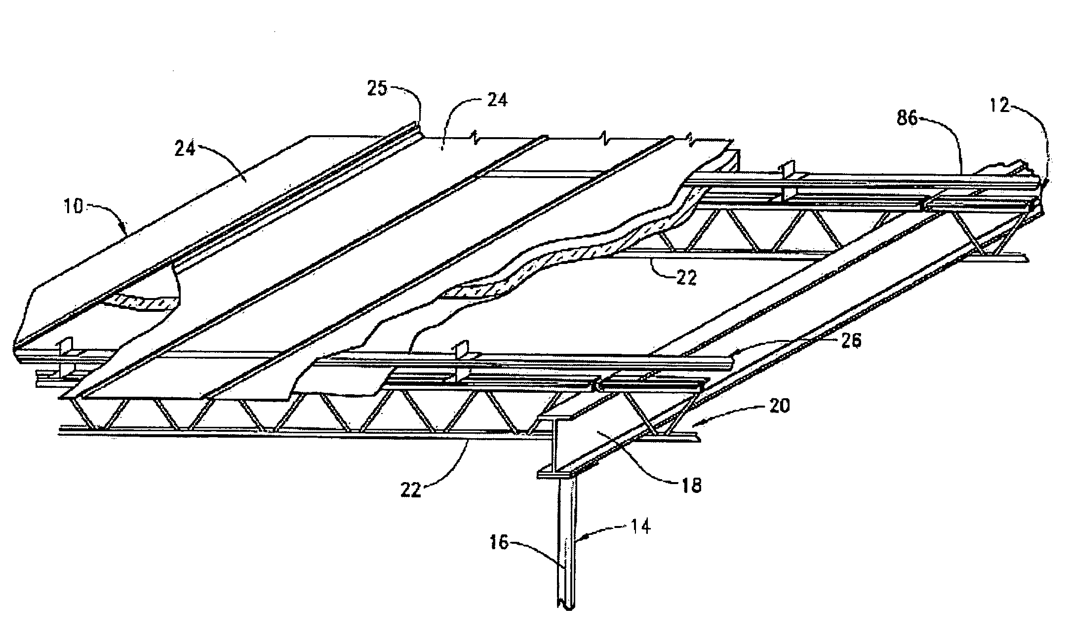
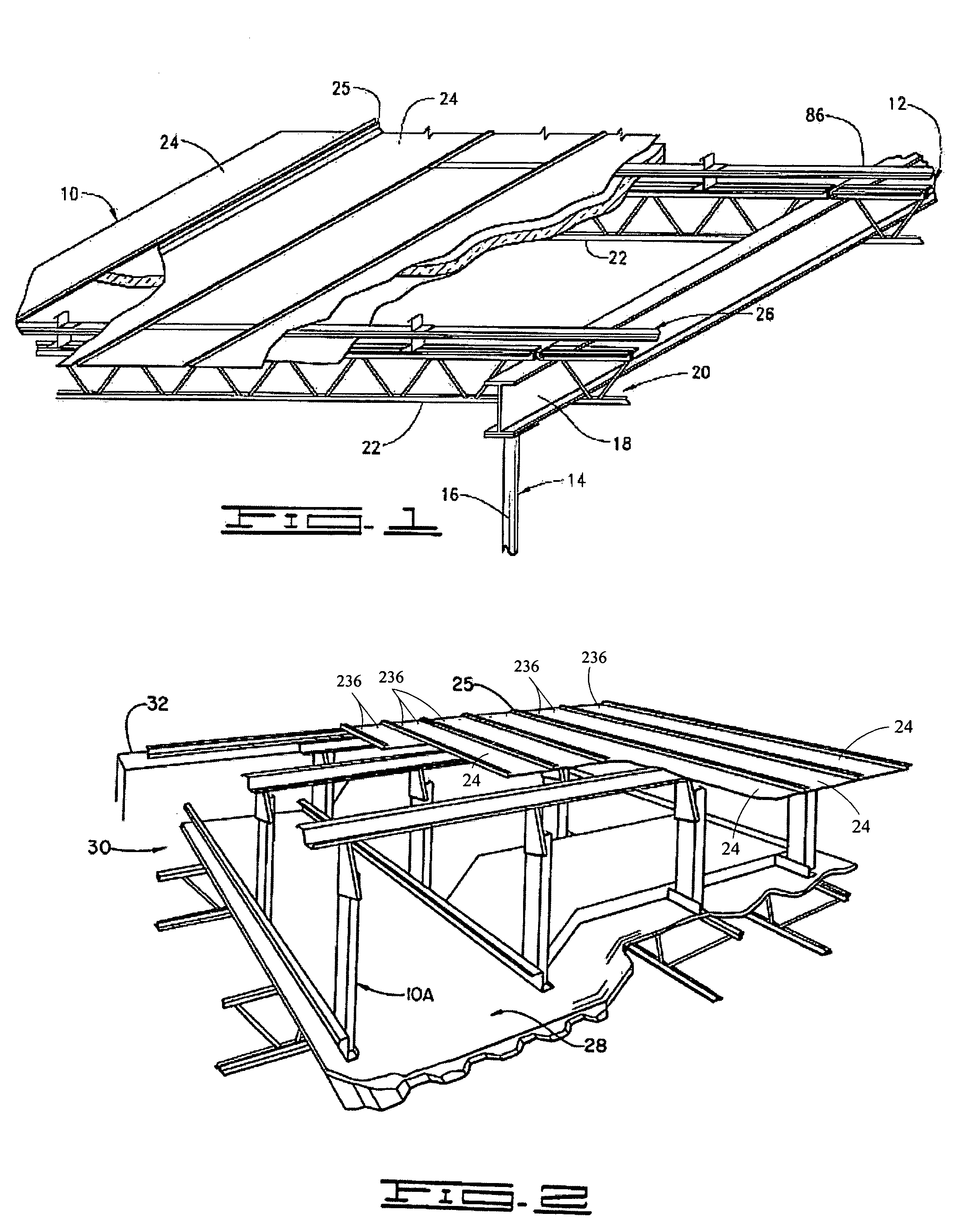
[0064]Referring to the drawings generally, and more particularly to FIG. 1, shown therein is a pre-engineered building roof 10 as supported by a pre-engineered building structure 12. The pre-engineered structure 12 comprises a primary structural system Sect. which consists of a plurality of upwardly extending column members 16 that are rigidly connected to a foundation (not shown). Also, the primary structural system 14 has a plurality of generally sloping primary beams 18 which are supported by the column members 16.

[0065]A secondary structural system 20 comprises a plurality of open web beams 22, also called bar joists, supported by the primary beams 18 generally in horizontal disposition. It will be understood that cee or zee purlins, or wood beams, can be used as the secondary structurals in lieu of the bar joists 22 in the practice of the present invention.

[0066]A plurality of roof panels 24 are supported over the secondary structural assembly 20 by a plurality of panel support...


PUM


Abstract

A roof assembly in which overlapping edges of adjacent panel members are joinable in an assembled mode to provide a seam having resistance to sidelap shear, the roof assembly comprising panels having a female sidelap along one edge and a male sidelap along the opposite edge, the female sidelap having a male insertion cavity and a leg member with a female retaining groove. The male sidelap, engageable in the male insertion cavity of an adjacent panel, has a tang lockingly disposed in the female retaining groove in folded tight adjacency to form a standing seam between panels. The panels are interconnected via backer plate fasteners to increase resistance to side slipping under wind uplift.

Description

RELATED APPLICATIONS[0001]This application is a continuation-in-part of U.S. patent application Ser. No. 09 / 978,262 filed Oct. 15, 2001, which is a continuation-in-part of 09 / 059,146 filed Apr. 13, 1998, now U.S. Pat. No. 6,301,853 issued Oct. 16, 2001. U.S. Pat. No. 6,301,853 is a continuation-in-part of U.S. patent application Ser. No. 08 / 484,975 filed Jun. 7, 1995, now U.S. Pat. No. 5,737,894 issued Apr. 14, 1998, and of U.S. patent application Ser. No. 08 / 480,968 filed Jun. 7, 1995, now U.S. Pat. No. 5,692,352 issued Dec. 2, 1997.FIELD OF THE INVENTION[0002]The present invention relates to a roof assembly for a building structure, and more particularly, but not by way of limitation, to a roof assembly having increased resistance to sidelap shear.BACKGROUND[0003]Numerous types of roof assemblies have previously been proposed for pre-engineered buildings in efforts to provide a watertight roof assembly, while also enabling the roof assembly to expand and contract as changes in tem...

Claims


Application Information

Patent Timeline
Patent Type & Authority Patents(United States)
IPC IPC(8): E04D1/00
CPCE04D3/362E04D15/04E04D3/363E04C2003/046E04D2003/3615
Inventor SIMPSON, HAROLD G.
Owner ENCON PROD INC
Why Eureka
Try Eureka