
Automatic transmission for a motorcycle

a technology of automatic transmission and motorcycle, which is applied in the direction of crankshaft transmission, frictional roller based transmission, cycle equipment, etc., can solve the problems of difficulty in reducing the size of the entire vehicle, the shift actuator is vulnerable to the heat and vibration of the engine, etc., and achieves the effect of reducing the influence of engine heat and vibration and reducing the posture of the driver

Active Publication Date: 2009-08-18
YAMAHA MOTOR CO LTD
View PDF19 Cites 19 Cited by
  • Summary
  • Abstract
  • Description
  • Claims
  • Application Information

AI Technical Summary

Benefits of technology

The present invention relates to a vehicle with a head pipe, body frame, and engine. The vehicle also has a transmission with a multiple-step shift mechanism and a clutch mechanism. An automatic transmission control unit operates the clutch mechanism and shifts the shift mechanism automatically. The shift actuator is mounted on the body frame and is connected to the shift mechanism through a shift-power transmission member, which reduces the impact of heat and vibration from the engine on the shift actuator. The vehicle also has a controller that synchronizes the operation of the clutch and shift mechanisms. The automatic transmission control unit is supported by the frame, which reduces the impact of the engine and transmission on the controller. The technical effects of the invention are improved performance and efficiency of the vehicle's transmission and reduced impact of external factors on the shift actuator.

Problems solved by technology

Since the shift actuator of the conventional automated manual transmission mechanism has been disposed behind the engine and directly on the engine, the shift actuator is vulnerable to the heat and vibration of the engine.
Also, since the shift actuator has been disposed between the engine and the body frame, a space for the shift actuator has been needed between the engine and the body frame, thus posing the problem of difficulty in reducing the size of the entire vehicle.

Method used


Image

  • Automatic transmission for a motorcycle
  • Automatic transmission for a motorcycle
  • Automatic transmission for a motorcycle

Examples


Embodiment Construction

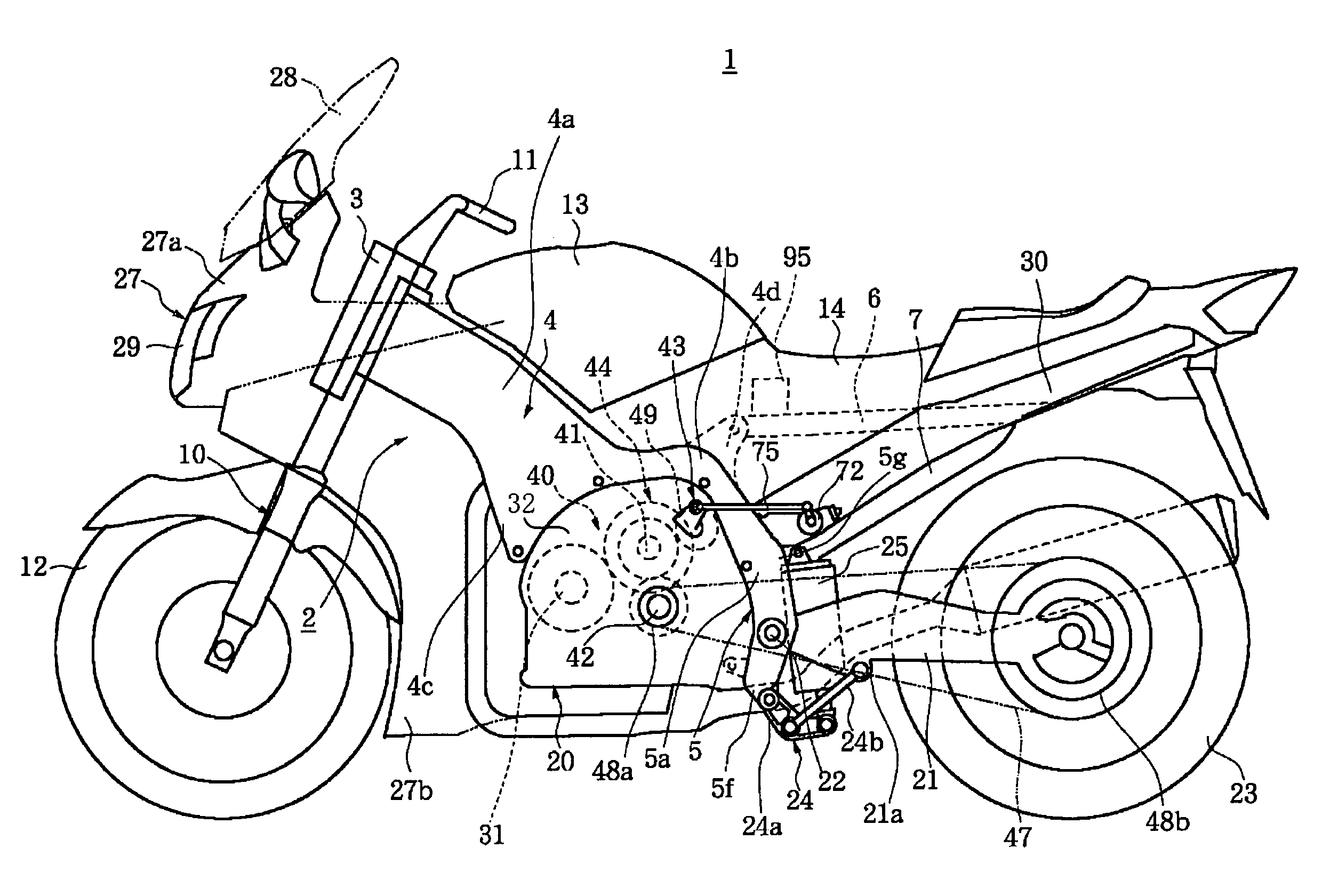
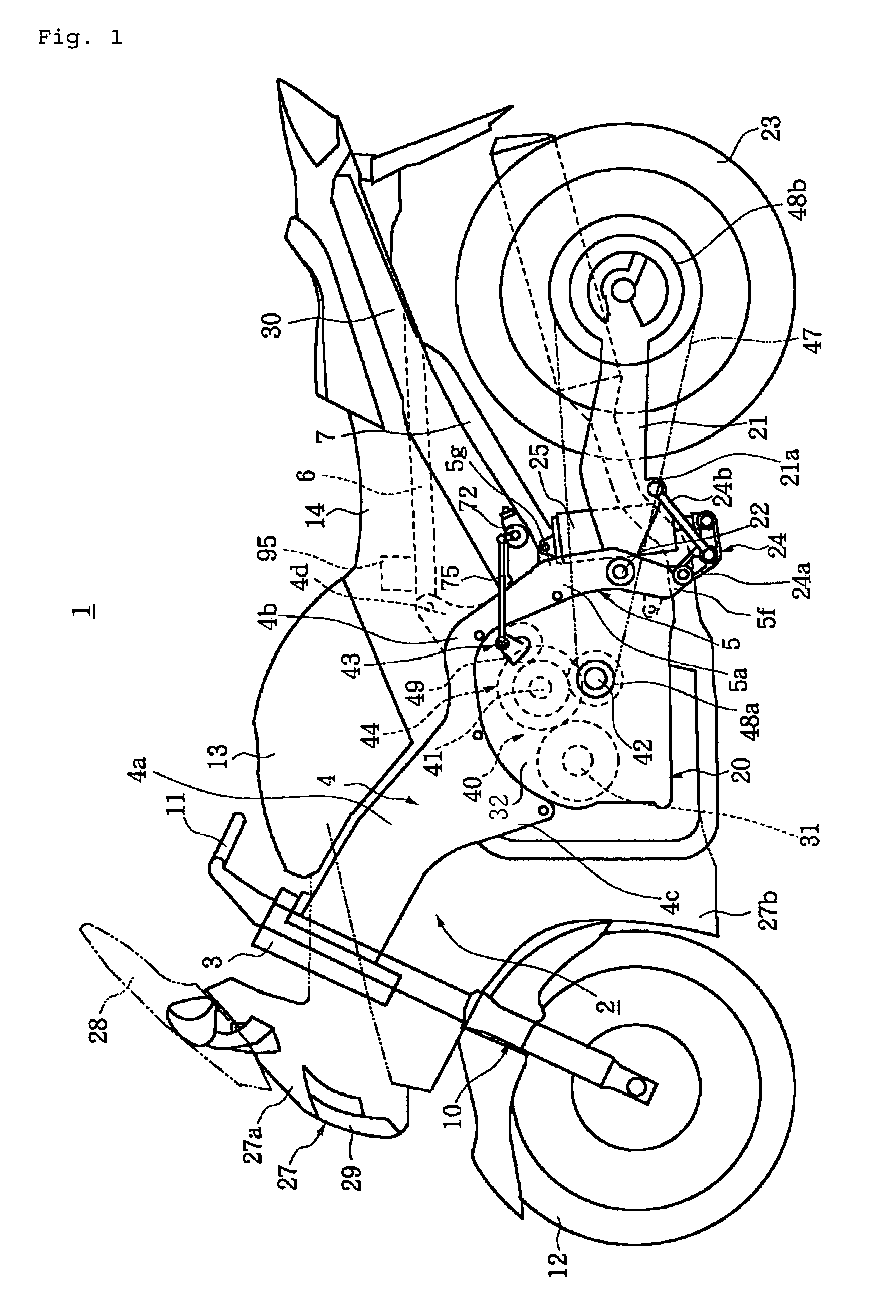
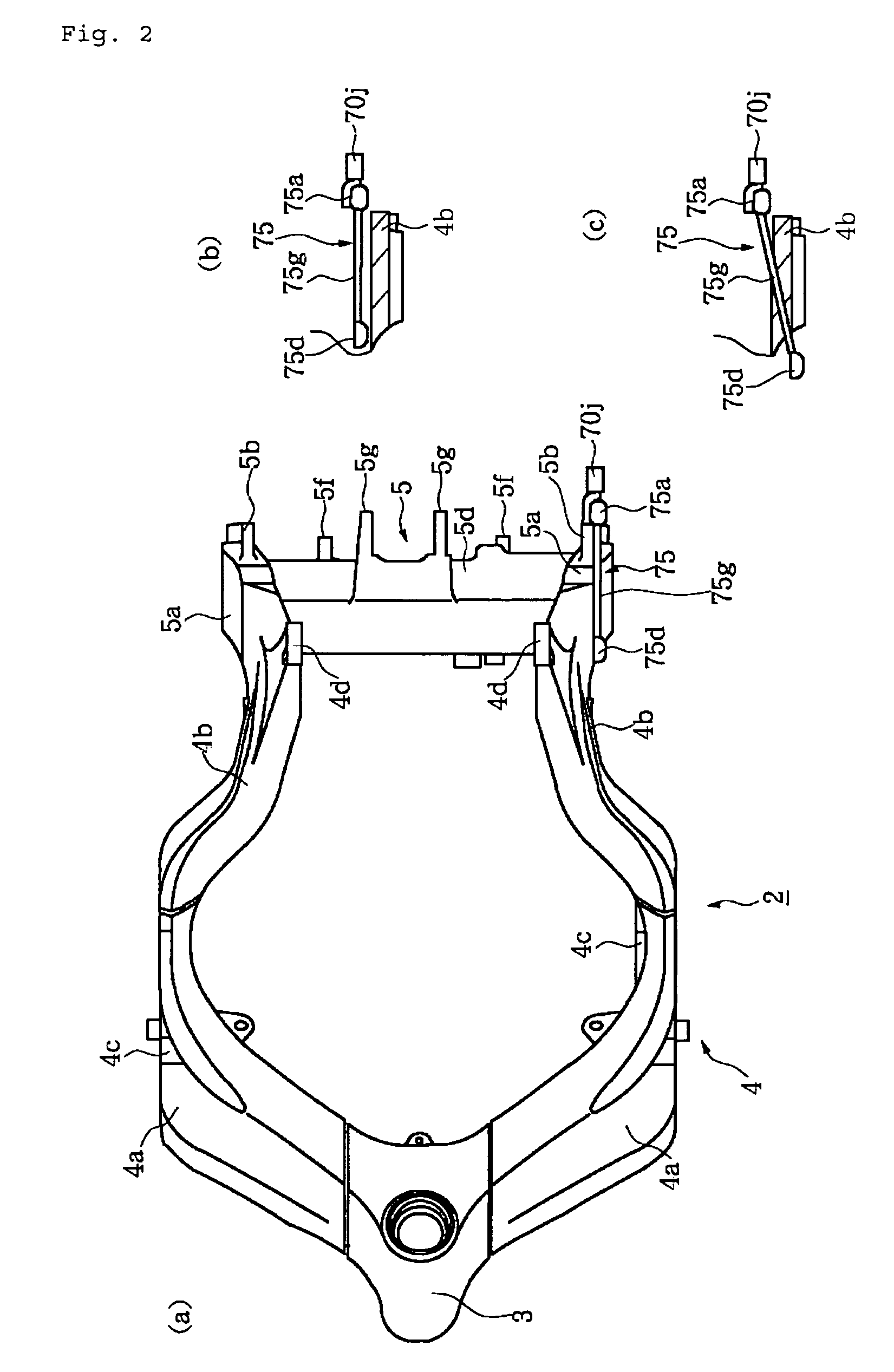
[0031]The present automatic transmission is described below in the context of a motorcycle. However, the application of the present invention is not so limited and can be employed with other types of vehicles, such as, for example, scooters, ATV's, dirt bikes, side-by-sides, buggies, tricycles, carts, and the like.

[0032]As shown in FIG. 1, a motorcycle 1 according to the embodiment includes a head pipe 3 and a body frame 2. The body frame 2 preferably includes at least a main frame 4 extending rearward from the head pipe 3 and a rear-arm bracket 5 extending downward from the rear of the main frame 4. As best seen in FIG. 2, the main frame 4 includes two frame members 4a that extend to the right and to left rear from the head pipe 3. The rears of the two frame members 4a slope downward to connect to the rear-arm bracket 5. As shown in FIGS. 2(a) and 3, the portions 4b of the frame members 4a, which connect to the rear-arm bracket 5, are bent inward along the width of the vehicle to f...


PUM


Abstract

In order to reduce the influences of engine heat and vibration on a shift actuator, a shift actuator is disposed apart from the engine and the transmission on a vehicle. In particular a straddle-type vehicle, the vehicle includes a head pipe and a body frame including a main frame that extends rearward from the head pipe. The engine is suspended by the body frame 2 and a transmission is disposed next to the engine. The transmission includes a shift mechanism having a multiple-step speed change gear and a clutch mechanism that interrupts the transmission of rotation at the switching of the speed change gear of the transmission 40. An automatic transmission control unit operates the clutch mechanism and switches the speed change gear of the transmission automatically. The automatic transmission control unit includes the shift actuator which is mounted to the body frame and is disposed opposite to the transmission with the body frame therebetween, as viewed from the side of the vehicle, for operating the shift mechanism. A shift rod joins together the shift mechanism and the shift actuator.

Description

CROSS-REFERENCE TO RELATED APPLICATIONS[0001]The present application is based on and claims priority under 35 U.S.C. § 119 to Japanese Patent Application No. 2004-307185, filed on Oct. 21, 2004; and Japanese Patent Application No. 2005-258821, filed Sep. 7, 2005, the entire contents of which is expressly incorporated by reference herein.BACKGROUND OF THE INVENTION[0002]1. Field of the Invention[0003]The present invention relates to a straddle-type vehicle that is improved in the arrangement of an automatic transmission control unit.[0004]2. Description of the Related Art[0005]Known straddle-type vehicles include motorcycles. Motorcycles generally have a transmission. The rotation of the crankshaft of an engine is changed by the transmission and transmitted to a powered wheel. The transmission includes a shift mechanism having a main shaft, a drive shaft, and a multiple-step speed change gear, and a clutch mechanism that interrupts the transmission of the rotation at the switching of...

Claims


Application Information

Patent Timeline
Patent Type & Authority Patents(United States)
IPC IPC(8): B62D61/02B62K11/02B60K17/06B60K20/00B62M25/06F16H61/28
CPCB62K11/04B62M7/00B62M25/06Y10T477/693625Y10T477/753
Inventor KOSUGI, MAKOTOIWANAGA, SADAMUMURAYAMA, TAKUJIMATSUDA, KIMIO
Owner YAMAHA MOTOR CO LTD
Learn More