Electrical connector with enhanced back end design

a back end design and connector technology, applied in the direction of coupling devices, two-part coupling devices, electrical apparatus, etc., can solve the problems of signal degradation, signal degradation, and little attention to the rear end of the jacks where the jacks are located

Active Publication Date: 2009-08-18
BISON PATENT LICENSING LLC
View PDF5 Cites 49 Cited by
  • Summary
  • Abstract
  • Description
  • Claims
  • Application Information

AI Technical Summary

Benefits of technology

[0006]In one embodiment, an electrical connector is provided. The electrical connector includes a back end sub-assembly including a back end housing extending along a longitudinal axis between a forward side and a rearward side. The back end housing defining a plurality of contact zones. At least one contact is held in each of the plurality of contact zones. A shield is provided within each of the plurality of contact zones with each shield at least partially surrounding at least one contact in the corresponding contact zone. Each shield is non-common with and does not electrically engage any other shield in the back end housing.
[0007]Optionally, each contact zone may include a single pair of contacts carrying differential signals. Each shield may be arranged at least partially between the associated contact zone and at least two other contact zones. Each contact zone may include more than two contacts. Optionally, the back end housing may be arranged in quadrants with each quadrant containing a single contact zone. Each shield being arranged between at least two adjacent quadrants. Each contact zone...

Problems solved by technology

One source of signal degradation is crosstalk between multiple signal paths.
The plugs are dictated by industry standards and are inherently susceptible to crosstalk, return loss and other phenomenon that lead to signal degradation.
However, heretofore, little attention has been paid to the rear end of the jacks where the jacks are connected to cables.
The design of the jacks and cables are susceptible to crosstalk ...

Method used


Image

  • Electrical connector with enhanced back end design
  • Electrical connector with enhanced back end design
  • Electrical connector with enhanced back end design

Examples


Embodiment Construction

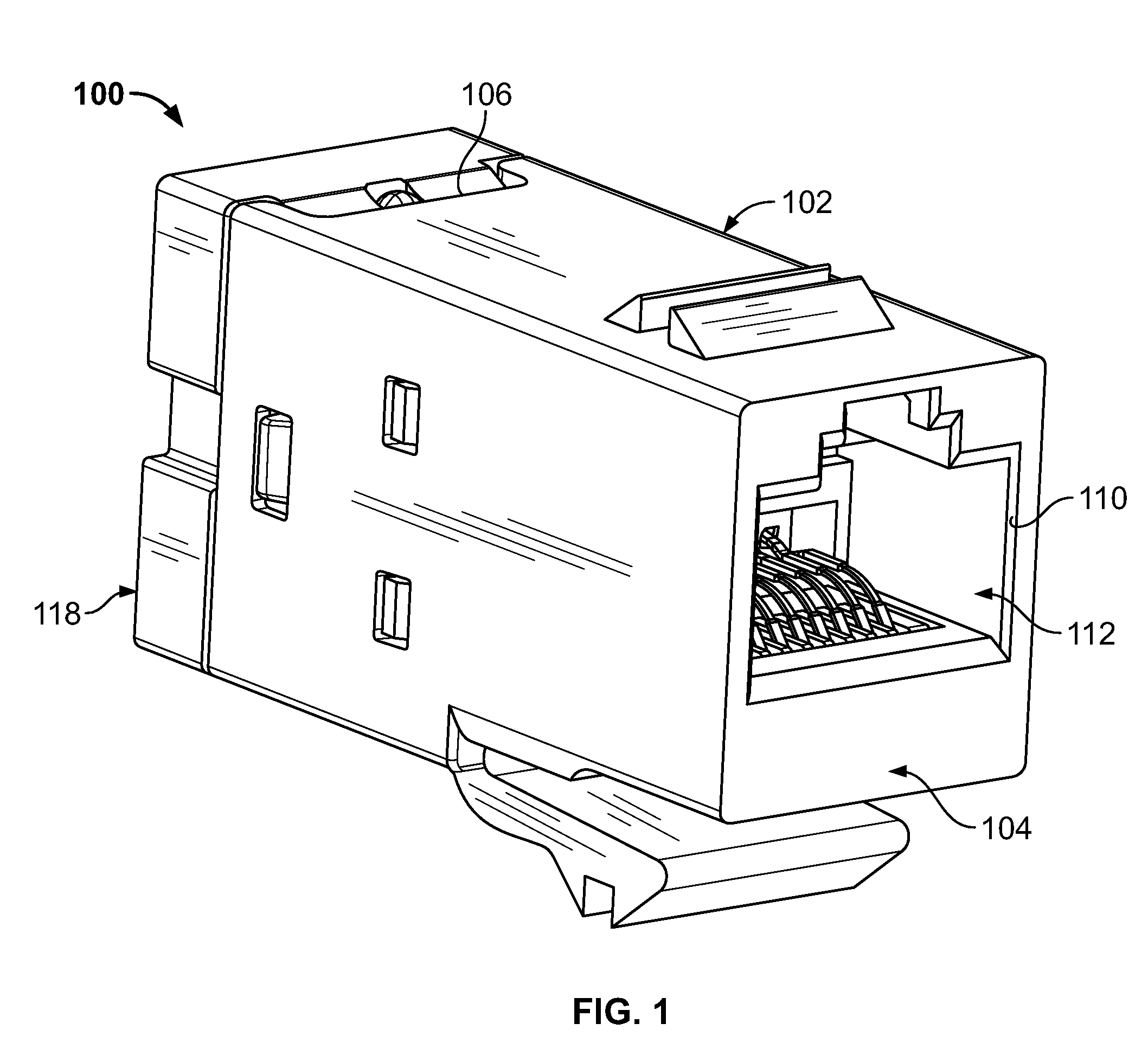
[0022]FIG. 1 is a perspective view of an electrical connector 100 formed in accordance with an exemplary embodiment. The connector 100, in an exemplary embodiment, is a modular jack that may be mounted on a wall or panel (not shown), or, alternatively, may be mounted in an electrical device or apparatus (not shown) having a communications port through which the device may communicate with other external networked devices. In the description that follows, the connector 100 will be described in terms of an RJ-45 jack. However, it is to be understood that the benefits described herein are also applicable to other connectors in alternative embodiments, including connectors including fewer or greater numbers of signal pairs. The following description is therefore provided for illustrative purposes only and is but one potential application of the subject matter described herein.

[0023]The connector 100 includes a housing 102 that has a forward mating end 104 and an opposite rearward cable ...


PUM


Abstract

An electrical connector includes a back end sub-assembly including a back end housing extending along a longitudinal axis between a forward side and a rearward side. The back end housing defining a plurality of contact zones. At least one contact is held in each of the plurality of contact zones. A shield is provided within each of the plurality of contact zones with each shield at least partially surrounding at least one contact in the corresponding contact zone. Each shield is non-common with and does not electrically engage any other shield in the back end housing.

Description

BACKGROUND OF THE INVENTION[0001]The subject matter herein relates generally to electrical connectors, and more particularly, to a connector jack having a standard plug interface combined with a back end design for improved connector performance.[0002]In electrical systems, such as telecommunications systems, there is increasing concern for preserving signal integrity as signal speed and bandwidth increase. One source of signal degradation is crosstalk between multiple signal paths. In the case of an electrical connector carrying multiple signals, crosstalk occurs when signals conducted over a first signal path are partly transferred by inductive or capacitive coupling into a second signal path. The transferred signals produce crosstalk in the second path that degrades the signal routed over the second path.[0003]One example of a typical connector for telecommunications systems is the industry standard type RJ-45 communication connector. Both plugs and jacks are provided for mating ...

Claims


Application Information

Patent Timeline
IPC IPC(8): H01R24/00
CPCH01R4/2433H01R13/6658H01R13/743H01R24/64Y10S439/941
Inventor PEPE, PAUL JOHNTOBEY, SHAWN PHILLIPMUIR, SHELDON EASTONBOPP, STEVEN RICHARDHOWER, JAMES SHANNON
Owner BISON PATENT LICENSING LLC
Why Eureka
Try Eureka