[0015]In one aspect of the present invention, a prosthetic disc for insertion between adjacent vertebrae includes a core having upper and lower curved surfaces and upper and lower plates. At least one of the curved surfaces of the core is composed of or covered by a metal, which forms a metallic portion of the core. Each plate has an outer surface which engages a vertebra and a metallic inner curved surface which is shaped to slide over one of the curved surfaces of the core. The center of rotation of the core is free to move relative to the upper and lower metallic plates. Thus, the plates can slide freely in all directions, not being limited to movement in a single direction as with the prior art. Metal endplates combined with a core having at least one metallic surface will help prevent wear and tear of the disc prosthesis.
[0016]“Curved surfaces” of the core and / or the plates typically means that such surfaces are spherical. However, it is also contemplated that other, non-spherical surface shapes may be used, such as but not limited to ovoid, crowned, domed or other complementary surface shapes which provide for the desired freedom of movement of the plates relative to the core. A center of rotation of the core that is free to move relative to the upper and lower plates means that the core is not fixed in an immobile state to either of the plates. Thus, the core may move laterally or “float” relative to the plates, and the plates may move freely over the core.
[0017]The upper and lower plates may be made of any suitable metal, metal alloy or combination of metals or alloys. In some embodiments, for example, the plates may be made of cobalt chrome molybdenum, titanium, stainless steel or some combination thereof. In some embodiments, titanium plates are used, and these plates may optionally include inner surfaces of titanium nitride and outer surfaces that are aluminum oxide blasted to create micro-concavities. In another embodiment, cobalt chrome plates are used, with the outer surfaces being blasted with aluminum oxide and then coated with a titanium plasma spray. In some embodiments, the plates comprise an MRI-compatible material, such as titanium, coupled with a hardened material, such as cobalt chrome molybdenum. Such materials may be coupled using any suitable means, such as welding, laminating, slip fitting, interference fitting, adhesion, welding, molding, heating and cooling one material to attach it to another, or the like. Some plates include a coating or material on the inner surfaces for reducing friction and / or wear and tear, such as a titanium nitride surface.
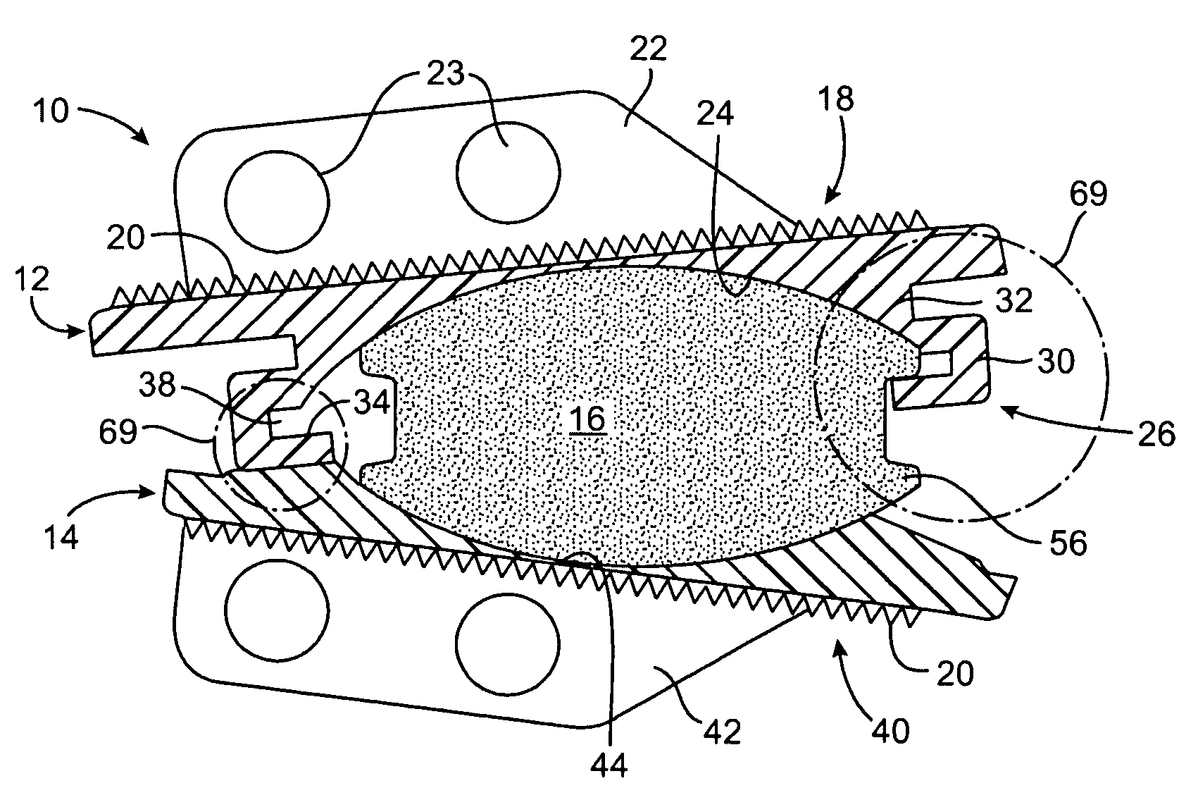
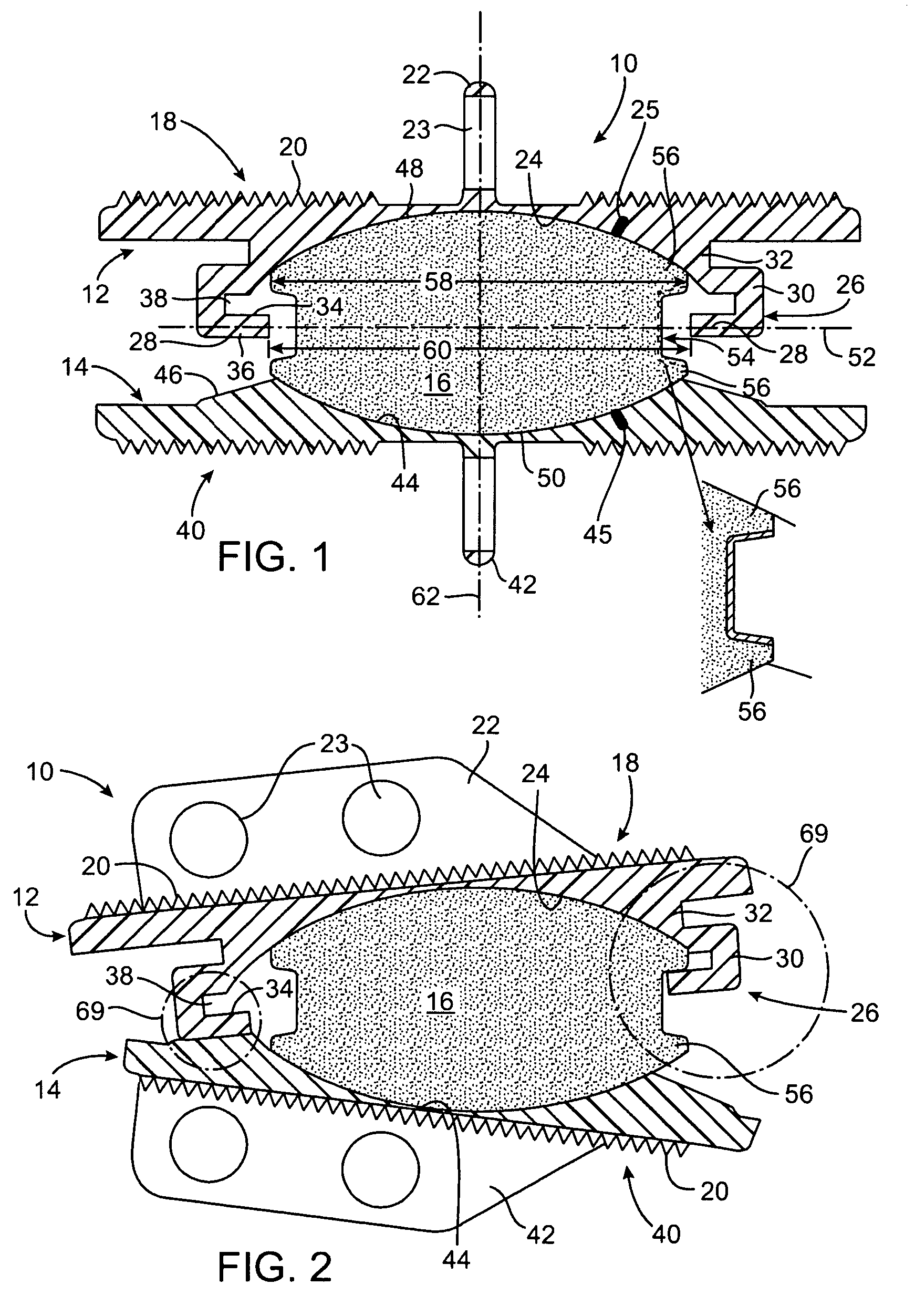
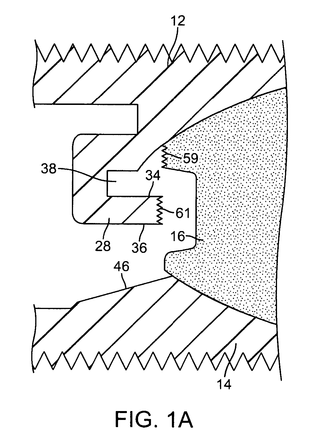
[0021]An advantage of the structure thus described is that the surface contact area between the core and each of the upper and lower plates may be maximized. By providing only a peripheral restraint, as opposed for example to grooves and keys on the surface of the core and plates, the width or diameter of the core relative to the size of the plate may be maximized. Moreover, the surfaces of the core and the plates which contact each other may be made smooth and free from other structure(s) that might adversely affect performance. In the preferred embodiments, both the curved surfaces of the plates and the corresponding surfaces of the core will be spherical sections. The use of spherical surfaces promotes free, unconstrained relative motion of the plates and the core in all directions.
[0022]In some embodiments, the peripheral restraining structure limits relative inclination of the plates during sliding movement of the plates over the core, usually by defining a stop structure. In other embodiments, the peripheral restraining structure lifts one side of the core relative to an opposite side of the core during sliding movement of the plates over the core. The peripheral restraining structure itself may take any of a number of different forms. In one embodiment, for example, the restraining structure comprises a ring structure on at least one of the upper and lower plates and an annular structure on at least a portion of the periphery of the core. In one embodiment, the ring structure is adapted to engage and restrain the annular structure on the core. For example, the ring structure may comprise a flange which defines an overhang over at least a portion of the periphery of one of the plates. The overhang of the flange will receive the annular structure on the core to provide an interference fit which retains the core against the curved surface of the plate but allows the core to slide freely and in an unconstrained manner within the limit or boundary defined by the flange. The annular structure on the core may be a rim which extends continuously or discontinuously (preferably continuously) around a lateral circumference of the core. By providing a rim which has a width, usually a diameter, which is slightly greater than the corresponding width of an inner edge of the flange at one point, the core will be held in place and will not be dislodged from the cavity defined by the ring structure in normal use.
[0023]In an alternative embodiment, the annular structure on the core may have a width or outer diameter that is slightly smaller than an inner diameter of the ring structure (such as a flange) on the upper or lower plate. Thus, the annular structure on the core may be passed through the ring structure to engage the core with the upper or lower plate. The core is then held in place, relative to the upper or lower plate, via forces applied by the adjacent vertebrae and surrounding soft tissue structures. Essentially, this embodiment is analogous to a ball-and-socket joint. Such an embodiment may be advantageous for ease of assembly of prosthetic disc with a metallic core and metallic endplates.

