Supercharge Your Innovation With Domain-Expert AI Agents!

Overcurrent detection circuit

a detection circuit and overcurrent technology, applied in the direction of power conversion systems, instruments, measurement devices, etc., can solve the problems of increasing power consumption, comparator b>56/b> may not be able to accurately detect overcurrent, and inability to take into account the on-resistance variations of output transistors caused by prior art circuits

Active Publication Date: 2009-08-18
NXP USA INC
View PDF8 Cites 7 Cited by
  • Summary
  • Abstract
  • Description
  • Claims
  • Application Information

AI Technical Summary

Benefits of technology

The solution effectively suppresses power consumption and chip area enlargement while maintaining accurate overcurrent detection across multiple levels, independent of on-resistance variations, enhancing the reliability and efficiency of the DC-DC converter systems.

Problems solved by technology

However, the prior art circuits do not take into consideration on-resistance variations of an output transistor caused by temperature or manufacturing process factors.
Similarly, in Japanese Laid-Open Patent Publication No. 6-311734, the comparator 56 may not be able to accurately detect overcurrent due to variations in the on-resistance of the switch element M14.
This increases power consumption and enlarges the chip area.
Thus, a single reference current generation circuit cannot detect multiple overcurrent levels.

Method used


Image

  • Overcurrent detection circuit
  • Overcurrent detection circuit
  • Overcurrent detection circuit

Examples


Embodiment Construction

[0015]In the drawings, like numerals are used for like elements throughout.

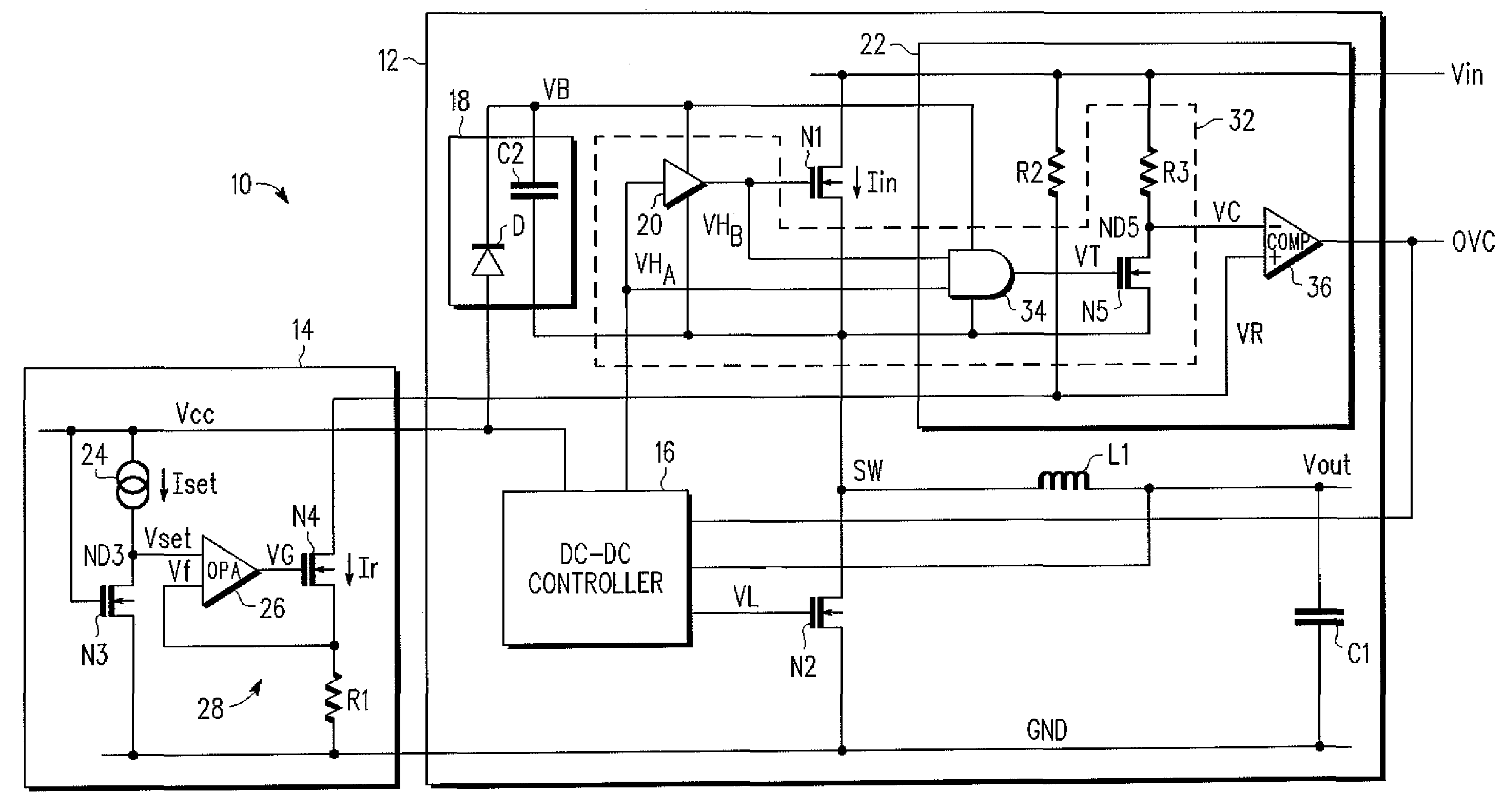
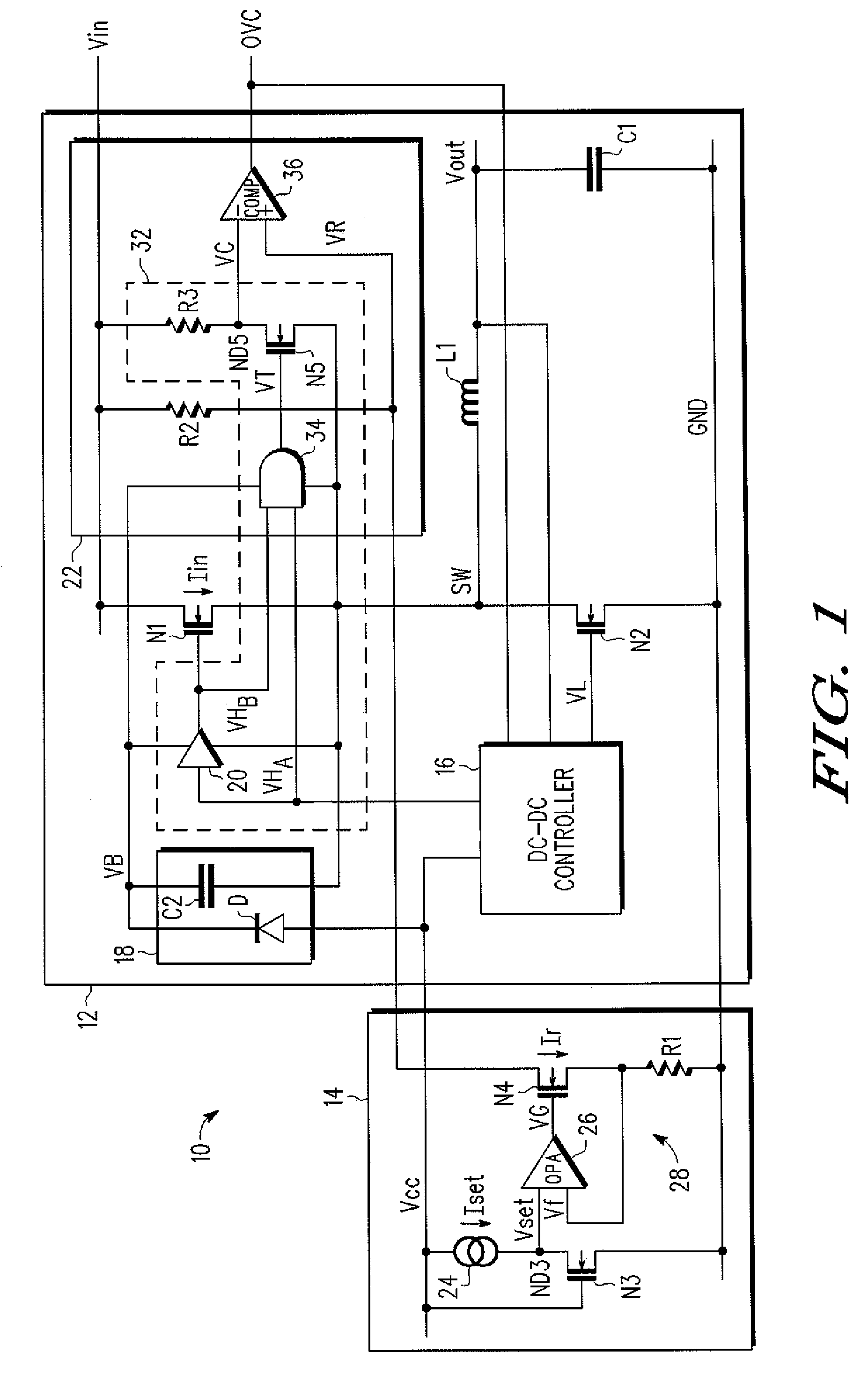
[0016]The present invention provides an overcurrent detection circuit that suppresses power consumption and chip area enlargement even when detecting multiple levels of overcurrent while preventing variations in the on-resistance of an output transistor from lowering the detection accuracy.

[0017]A first aspect of the present invention is an overcurrent detection circuit for detecting overcurrent flowing to an output transistor. The overcurrent detection circuit includes a constant current circuit for generating a reference current. A replica transistor, connected to the constant current circuit, generates a reference voltage that is in accordance with the reference current. A voltage-current conversion circuit, connected to the constant current circuit and the replica transistor, generates a determination reference current that is proportional to the reference current based on the reference voltage. A current...


PUM


Abstract

A circuit for detecting overcurrent flowing to an output transistor. A replica transistor generates a reference voltage that is in accordance with a reference current flowing from a constant current circuit. A voltage-current conversion circuit generates a determination reference current proportional to the reference current based on the reference voltage. A current-voltage conversion circuit converts the determination reference current to a determination reference voltage. A detector detects overcurrent flowing to the output transistor based on the determination reference voltage.

Description

BACKGROUND OF THE INVENTION[0001]The present invention relates to an overcurrent detection circuit, and more specifically, to an overcurrent detection circuit for use in a power supply circuit for a DC-DC converter or the like.[0002]In the prior art, a power supply circuit for a DC-DC converter or the like drives an output transistor to control current that is supplied to a load. Normally, a power supply circuit includes an overcurrent detection circuit to detect overcurrent flowing to the output transistor and protect the power supply circuit from the overcurrent.[0003]Japanese Laid-Open Patent Publication No. 2003-224968 describes a differential amplifier 1 that detects overcurrent flowing to a switching element M1 (output transistor) based on a reference voltage source V1 (see FIG. 1 of the publication). Japanese Laid-Open Patent Publication No. 6-311734 discloses a comparator 56 for detecting overcurrent flowing to a switch element M14 (output transistor) by comparing an output ...

Claims


Application Information

Patent Timeline
Patent Type & Authority Patents(United States)
IPC IPC(8): G05F1/573
CPCG01R19/16538G05F1/573G01R19/16571
Inventor KIMURA, HIROYUKI
Owner NXP USA INC
Features
  • R&D
  • Intellectual Property
  • Life Sciences
  • Materials
  • Tech Scout
  • Unparalleled Data Quality
  • Higher Quality Content
  • 60% Fewer Hallucinations
Learn More