Low power DC-DC converter with improved load regulation

a low-power, load regulation technology, applied in the field of electrical circuits, can solve problems such as general undesirable undesirable variations in the output voltage of converters, and achieve the effect of improving the load regulation and reducing the voltage of the converter

Active Publication Date: 2009-08-18
MARVELL ASIA PTE LTD
View PDF9 Cites 41 Cited by
  • Summary
  • Abstract
  • Description
  • Claims
  • Application Information

AI Technical Summary

Benefits of technology

[0006]A voltage converter, in accordance with one embodiment of the present invention, includes, in part, an amplifier and a comparator. The amplifier is responsive to a first reference voltage and to a first feedback voltage representative

Problems solved by technology

Uncontrolled variations in converter ou

Method used


Image

  • Low power DC-DC converter with improved load regulation
  • Low power DC-DC converter with improved load regulation
  • Low power DC-DC converter with improved load regulation

Examples


Embodiment Construction

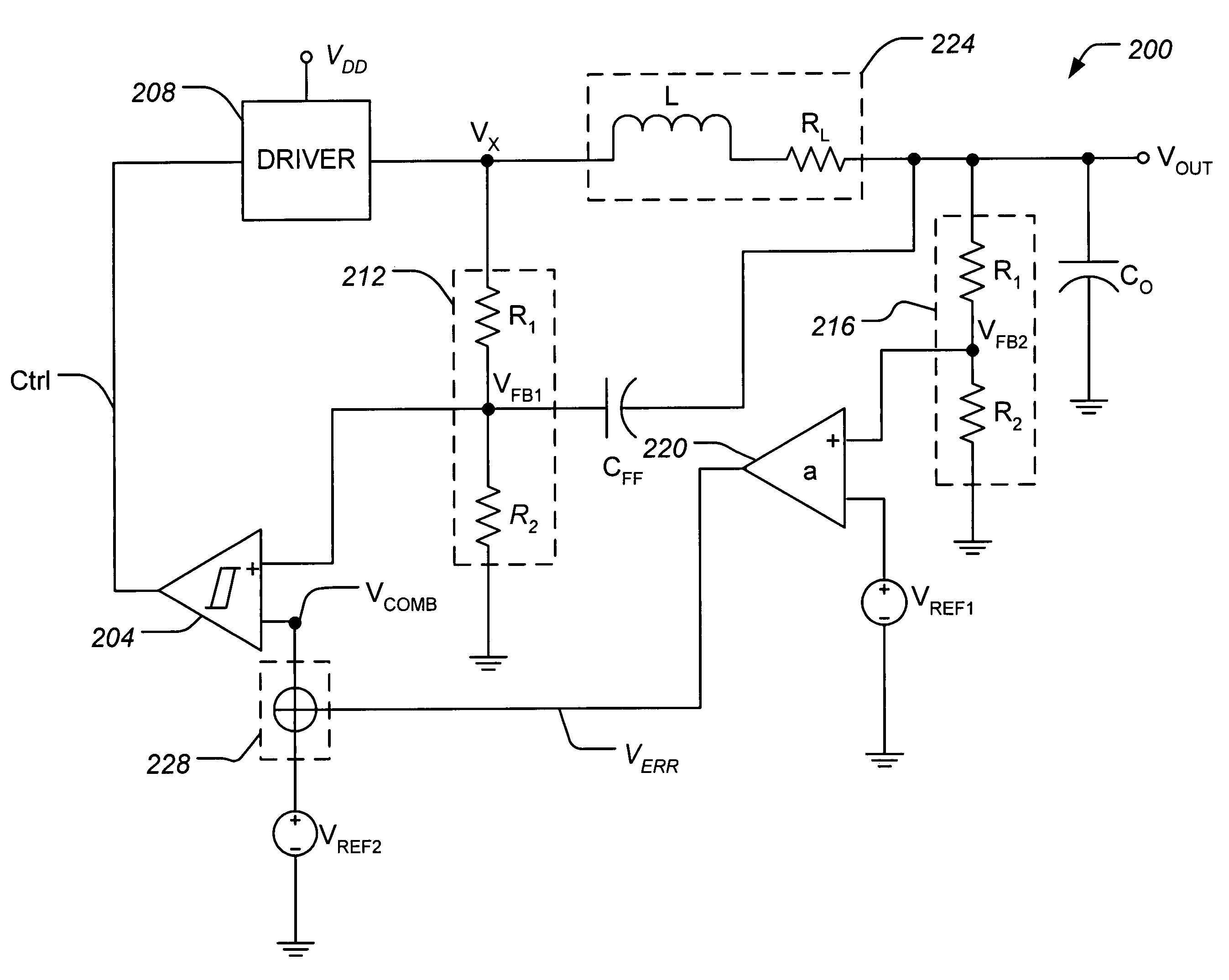
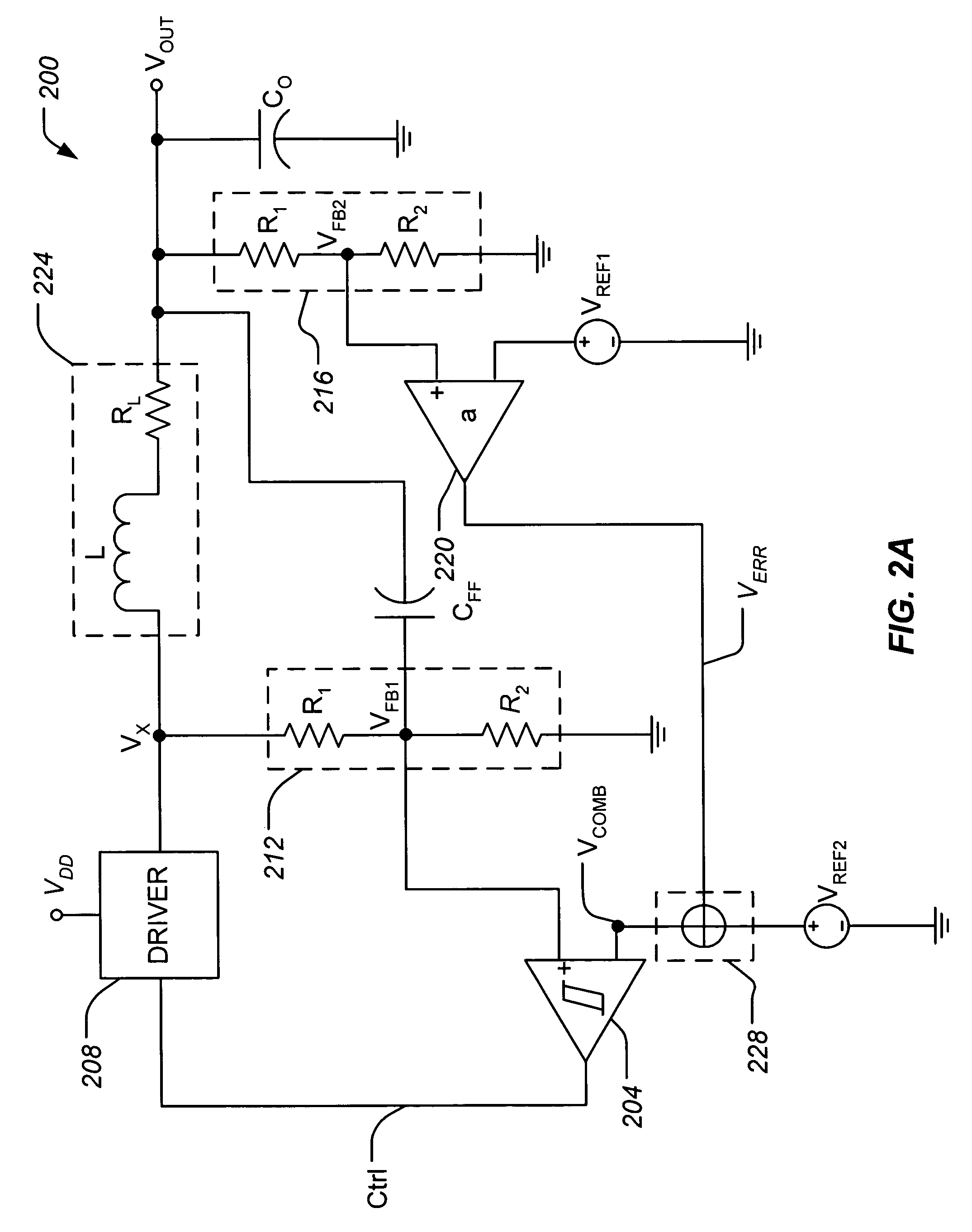
[0023]A voltage converter in accordance with one embodiment of the present invention includes, in part, an amplifier, a voltage combiner, a hysteretic comparator, and a driver. The amplifier generates an error voltage signal representative of a voltage drop across an inductor disposed in the voltage converter. The voltage combiner combines the error voltage signal with a first reference voltage to generate a combined voltage signal. The hysteretic comparator compares the combined voltage signal to a feedback voltage signal and generates a control signal. The driver receives the control signal and causes a corresponding increase or decrease in the driver output voltage. Because the voltage drop across the resistive load of the inductor is reduced by a factor corresponding to the gain of the amplifier, uncontrolled variations in the converter output voltage are avoided.

[0024]FIG. 2A shows a simplified block diagram of a voltage converter 200 according to an embodiment of the present i...


PUM


Abstract

A voltage converter includes, among other things, an amplifier, a voltage combiner, and a hysteretic comparator. The amplifier has a first input terminal which receives a first voltage representative of an output voltage of the voltage converter, a second input terminal which receives a first reference voltage, and an output terminal which generates a second voltage proportional to a difference between the first voltage and the first reference voltage. The voltage combiner combines the second voltage with a second reference voltage to generate a combined voltage. The comparator causes a third voltage to decrease if a feedback voltage defined by the third voltage is detected by the comparator as being greater than a first threshold voltage defined by the combined voltage, and further to cause the third voltage to increase if the feedback voltage is detected by the comparator as being less than the first threshold. The third voltage is applied to a first terminal of a load external to the voltage converter.

Description

BACKGROUND OF THE INVENTION[0001]The present invention relates generally to electronic circuits and, more particularly to conversion of voltages used in such circuits.[0002]There is often a need to generate a lower DC output voltage from a higher DC input voltage in devices that contain integrated circuits (IC). Voltage converters that perform this function attempt to maintain a stable output voltage and to respond quickly to load transients. Uncontrolled variations in converter output voltage are generally undesirable.[0003]One known circuit for converting voltages is shown in FIG. 1. Voltage converter 100 generates output voltage VOUT from input voltage VIN. As shown, voltage converter 100 includes, in part, a comparator 104 with input hysteresis, a reference voltage generator VREF, a driver 108, an LC filter 116, a voltage divider 112, and a capacitor CFF. Hysteretic comparator 104 generates a control signal Ctrl by comparing reference voltage VREF to a feedback voltage VFB. If f...

Claims


Application Information

Patent Timeline
IPC IPC(8): G05F1/575
CPCH02M3/1563H02M2001/0009H02M1/0009
Inventor ZHANG, JIANCHENGDAI, SHAOAN
Owner MARVELL ASIA PTE LTD
Why Eureka
Try Eureka