Proximity detection and communication mechanism and method

a communication mechanism and proximity technology, applied in the direction of navigation instruments, instruments, roads, etc., can solve the problems of loss of detection, increased maintenance costs, inaccurate indications, etc., and achieve the effect of facilitating testing the mechanism

Active Publication Date: 2009-08-18
C D L ELECTRIC CO INC
View PDF16 Cites 62 Cited by
  • Summary
  • Abstract
  • Description
  • Claims
  • Application Information

AI Technical Summary

Benefits of technology

[0010]The present invention overcomes the above-described and other problems and disadvantages in the prior art by providing a vital proximity detection mechanism and method for use in determining the position, i.e., normal or reverse, of railroad switch points relative to first and second stock rails or fixed tracks, and providing a output signals indicative of the switch point positions which may be used to communicate the determined position to a railroad signaling device or the like. The mechanism uses two substantially separate circuits to allow for cross-checking and redundancy to ensure proper and reliable operation. By default, the critical signal device will be energized only if all criteria are met. In addition, the output signals which are produced by the circuits are electrically isolated from the power source to prevent a false output signal if the circuits are damaged. The mechanism is designed to meet applicable AREMA safety standards and specifications for vital componentry and devices.
[0012]The first and second proximity sensors independently generate first and second electronic sensor signals indicative of the proximity of the switch points to the normal position or first alignment, and the third and fourth proximity sensors independently generate third and fourth electronic sensor signals indicative of the proximity of the switch points to the reverse position or second alignment. The present invention's use of two proximity sensors for each position provides operational redundancy and enhanced reliability, as discussed below in greater detail. The output of each of the proximity sensors is applied to the input of each of the microprocessors.
[0015]The diodes are connected to an output conductor for each of the power supplies between the power supply and the associated terminal. The diodes prevent electronic feedback between the first and second power supplies or the third and fourth power supplies via the associated output conductors. The first output terminals provide an output signal for use in controlling the delivery of power to the normal signal device, while the second output terminals provides an output signal for use in controlling the delivery of power to the reverse signal device.
[0017]The RF transmitter receives input from the microprocessors regarding the statuses of the proximity sensors and relays. This information is transmitted by the RF transmitter via an RF signal. The remote status indicator unit facilitates testing the mechanism by receiving the RF signal and visually communicating these statuses. This allows a technician to position him- or herself at the location of the proximity sensor, which may be substantially removed from the microprocessors, and make adjustments thereto while monitoring the results of those adjustments as determined by the microprocessors.

Problems solved by technology

Thus, for example, a train may expect the switch point to be in a normal position and therefore to proceed onto the main track, only to discover that the prior art switch point position detection mechanism is malfunctioning and the train is, in fact, moving onto the branch track at an unsafe speed which may cause it to derail.
However, these prior art switch point position detection mechanisms suffer from a number of other problems and disadvantages that can cause a loss of detection or an inaccurate indication of switch point position, the consequences of which include increased maintenance costs and increased risks of train delays or derailments.
These problems and disadvantages include, for example, loose or worn connecting rod linkages; loose or worn bolts or screws that fasten the prior art controller box to the ties or plates; worn bearings, connections, or contacts in the prior art controller box; improper adjustment of cams, contacts, and linkages; shorted, open, or crossed wirings due to mechanical damage, rodent damage, and various other causes; running rails; and labor-intensive installation maintenance, inspection, and adjustment requirements.

Method used


Image

  • Proximity detection and communication mechanism and method
  • Proximity detection and communication mechanism and method
  • Proximity detection and communication mechanism and method

Examples


first embodiment

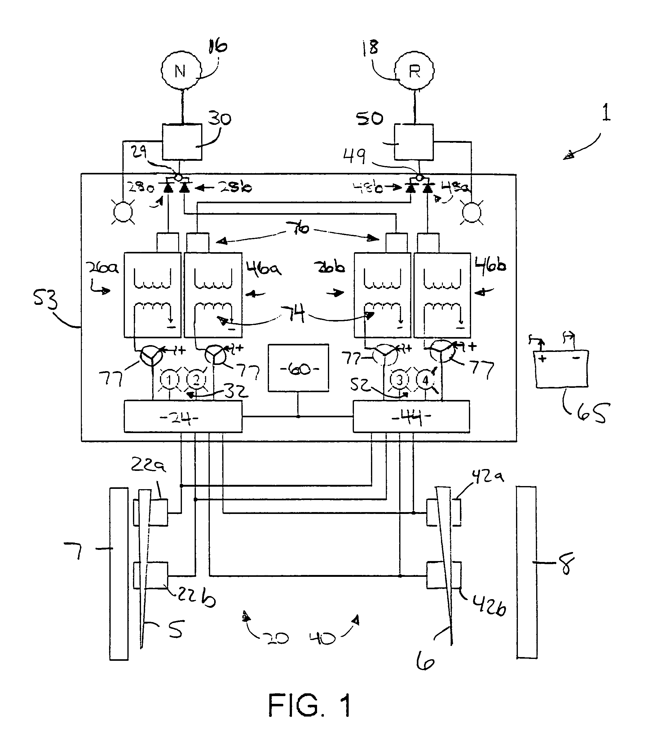
[0021]FIG. 1 is a block diagram showing major components of a preferred first embodiment of the vital proximity detection mechanism of the present invention;

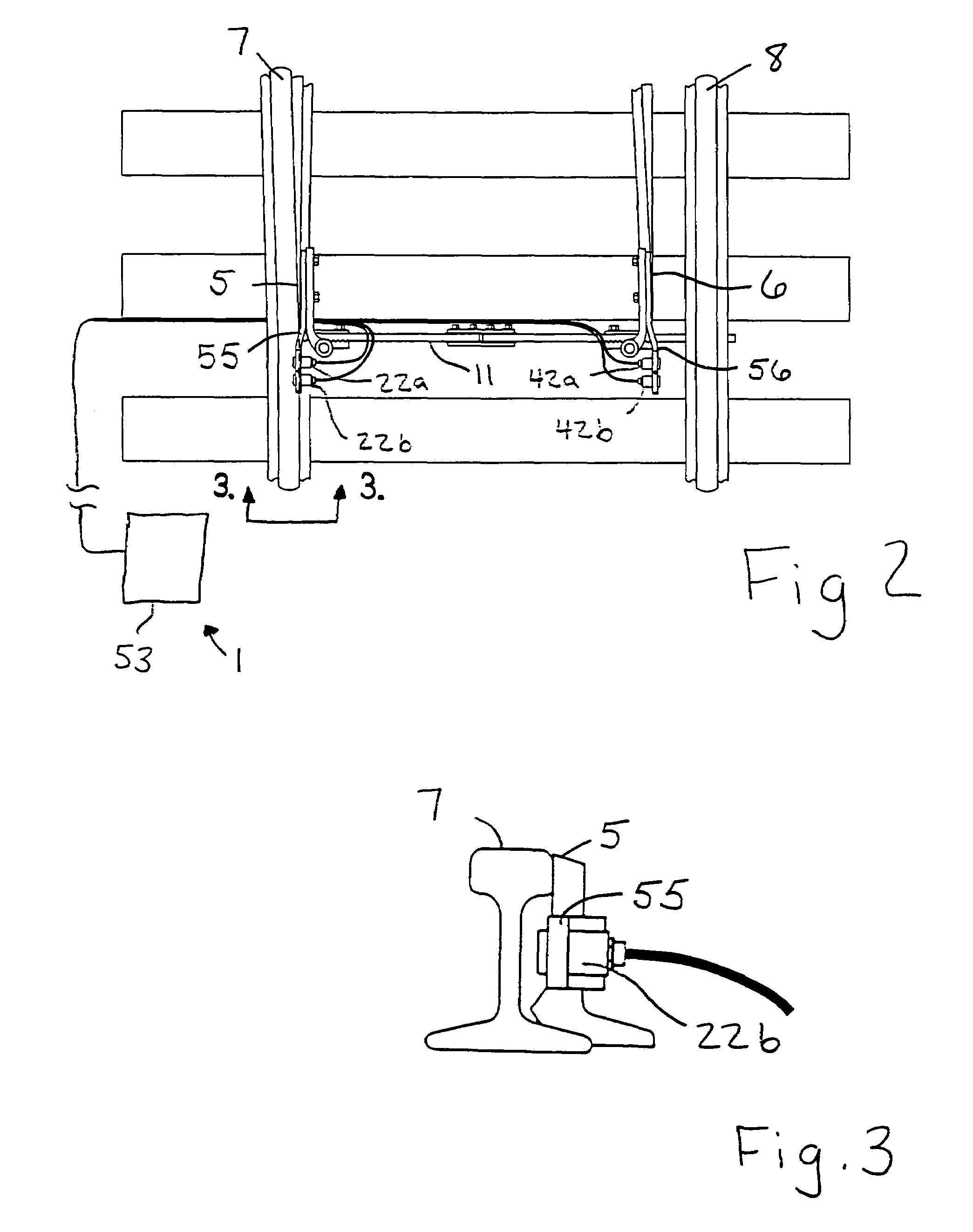
[0022]FIG. 2 is a fragmentary top plan view showing placement of first, second, third and fourth proximity sensor components of the present invention relative to rail switch points;

[0023]FIG. 3 is a fragmentary cross-sectional elevation view taken along line 3-3 of FIG. 2;

[0024]FIG. 4 is a front view of a remote status indicator unit for use in testing the mechanism of FIG. 1;

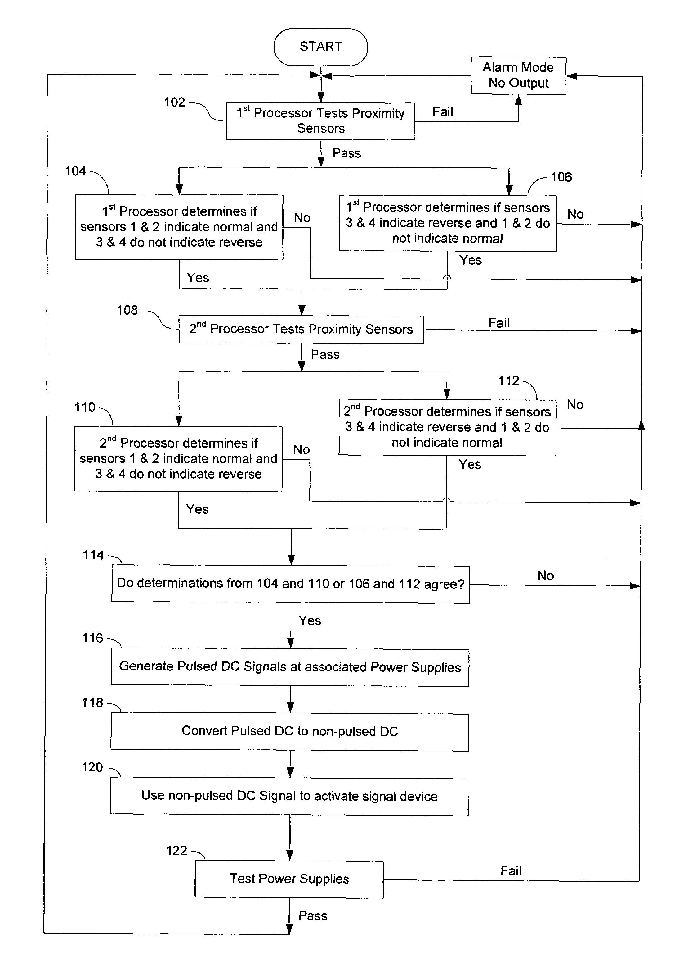
[0025]FIG. 5 is a flowchart showing steps involved in operation of the mechanism of FIG. 1.

second embodiment

[0026]FIG. 6 is a block diagram showing major components of a preferred second embodiment of the vital proximity detection mechanism of the present invention;

DETAILED DESCRIPTION OF A PREFERRED EMBODIMENT

[0027]With reference to the figures, a vital proximity detection (VPD) mechanism 1 and method is herein described, shown, and otherwise disclosed in accordance with a preferred embodiment of the present invention. The mechanism 1, a preferred embodiment of which is shown schematically in FIG. 1, is an electronic solid-state device for determining a proximity and alignment of a first part or member relative to a second part or member within a tolerance required by the particular application. In one contemplated application, as generally shown in FIG. 2, the mechanism 1 is adapted for use in determining the position of a normal and reverse switch points 5 and 6 relative to first and second stock rails 7 and 8 and more specifically for providing output signals indicative of whether the...


PUM


Abstract

A vital proximity detection mechanism and method for reliably determining and communicating the position of a railroad switch point relative to a normal fixed track and a reverse fixed track, wherein the mechanism includes substantial component redundancy and fault-checking features and otherwise meets promulgated safety standards for vital componentry. The mechanism includes an RF transmitter and remote status indicator unit to allow for remote adjustments of proximity sensors while monitoring the effects of such adjustments.

Description

BACKGROUND OF THE INVENTION[0001]1. Field of the Invention[0002]The present invention relates to position sensing mechanisms and methods including mechanisms and systems for determining the position of members such as railroad switch points. More particularly, the present invention concerns a vital proximity detection mechanism and method for reliably determining and communicating the position, e.g., normal or reverse, of railroad switch points relative to one or more fixed tracks, wherein the mechanism includes substantial component redundancy and fault-checking features and otherwise meets promulgated safety standards for vital componentry.[0003]2. Description of the Related Art[0004]It is often necessary to direct trains from one track onto another. This is accomplished with a switch comprising a pair of movable rails with tapered ends or switch points. The switch points are selectively moveable between a pair of stock rails to direct the train toward one of two diverging tracks ...

Claims


Application Information

Patent Timeline
Patent Type & Authority Patents(United States)
IPC IPC(8): G06F7/00B61L1/00E01B7/00
CPCB61L5/102
Inventor HENRY, WILLIAM L.KILGORE, STEPHEN V.
Owner C D L ELECTRIC CO INC
Why Eureka
Try Eureka