Apparatus and method for demetallizing a metallized film

a technology of metallized film and apparatus, which is applied in the direction of pattern printing, printing presses, printing, etc., can solve the problems of high corrosive material handling, inefficient operation, and the type of selective etching method may suffer several problems, so as to speed up the process for rapid assembly line use, avoid undesirable heating of corrosive baths or etchant soaked rollers

Active Publication Date: 2009-08-25
WATKINS JEFFREY T
View PDF24 Cites 2 Cited by
  • Summary
  • Abstract
  • Description
  • Claims
  • Application Information

AI Technical Summary

Benefits of technology

[0014]The above-noted disadvantages of the prior art are overcome by the present invention, which in one aspect is a method of demetallizing a metallized film. In one embodiment, the method uses conventional flexographic printing to apply an etchant solution to a moving metallized film. In one example, the film is at least partially wrapped onto a heat transfer device, such as, for example, a heat transfer roller and is directly printed with a patterned etchant solution from a pattern transfer roller. This method results in efficient heat transfer to the patterned demetallizing process thus speeding the process for rapid assembly line use while avoiding undesirable heating of corrosive baths or etchant soaked rollers. The process is fast enough to allow direct lamination of the patterned film to a backing paperboard without rinsing or barrier coating.
[0015]The etching solution used in the present invention may be of relatively low concentration and / or low pH. The temperatures utilized by the heat transfer device may be quite high as the film is partially wrapped around the heat transfer roller to control film distortion and because the etching effectiveness is enhanced at elevated temperatures. Normally, the etching solution is not heated prior to application to the metallized film to minimize problematic drying of the solution on heated rollers and the viscosity and evaporative concentration changes inherent in heated solution baths.
[0016]The present invention provides for fine demetallizing patterns that are easily realized with few steps. The etchant solution is not washed over the portions of the film that are to remain metallized and there is no required etchant resistant masking. Further, the possibility of etchant solution drift due to squeezing during lamination prior to complete etching is minimized or avoided.

Problems solved by technology

However, the latter involves the problematic handling of highly corrosive materials.
This type of selective etching method may suffer several problems.
The direct heating of the etchant solution, on the wet roller, may cause undesirable drying which does not efficiently serve the needs to apply the solution to the metallized film.
A metal may become distributed non-uniformly into tiny islands upon the backing film, and such an arrangement does not provide for the efficient conversion of radiant microwave energy to useful thermal energy.
However, this method may have a number of disadvantages.
Still another disadvantage is that when the (wet) demetallizing solution is pressed onto the adjacent sheet, the previously undisturbed pattern may squeeze out resulting in loss of the intended pattern.
In addition to the drawbacks in drying the film this process has an additional flaw.
This process typically uses a high pH solution that is printed with conventional printing methods and such hot “inks” do not print well because the “caustic ink” tends to dry on plates, rollers, etc. before being transferred to the substrate.
Furthermore, the rinsing operation becomes very critical because the caustic typically has come in contact with the areas that are not to be demetallized.

Method used


Image

  • Apparatus and method for demetallizing a metallized film
  • Apparatus and method for demetallizing a metallized film
  • Apparatus and method for demetallizing a metallized film

Examples


Embodiment Construction

[0028]The present invention is more particularly described in the following examples that are intended to be illustrative only since numerous modifications and variations therein will be apparent to those skilled in the art. As used in the specification and in the claims, the singular form “a,”“an” and “the” include plural referents unless the context clearly dictates otherwise. Also, the meaning of “in” includes “in” and “on” unless the context clearly dictates otherwise. Referring to the drawing, like numbers indicate like parts throughout the figures.

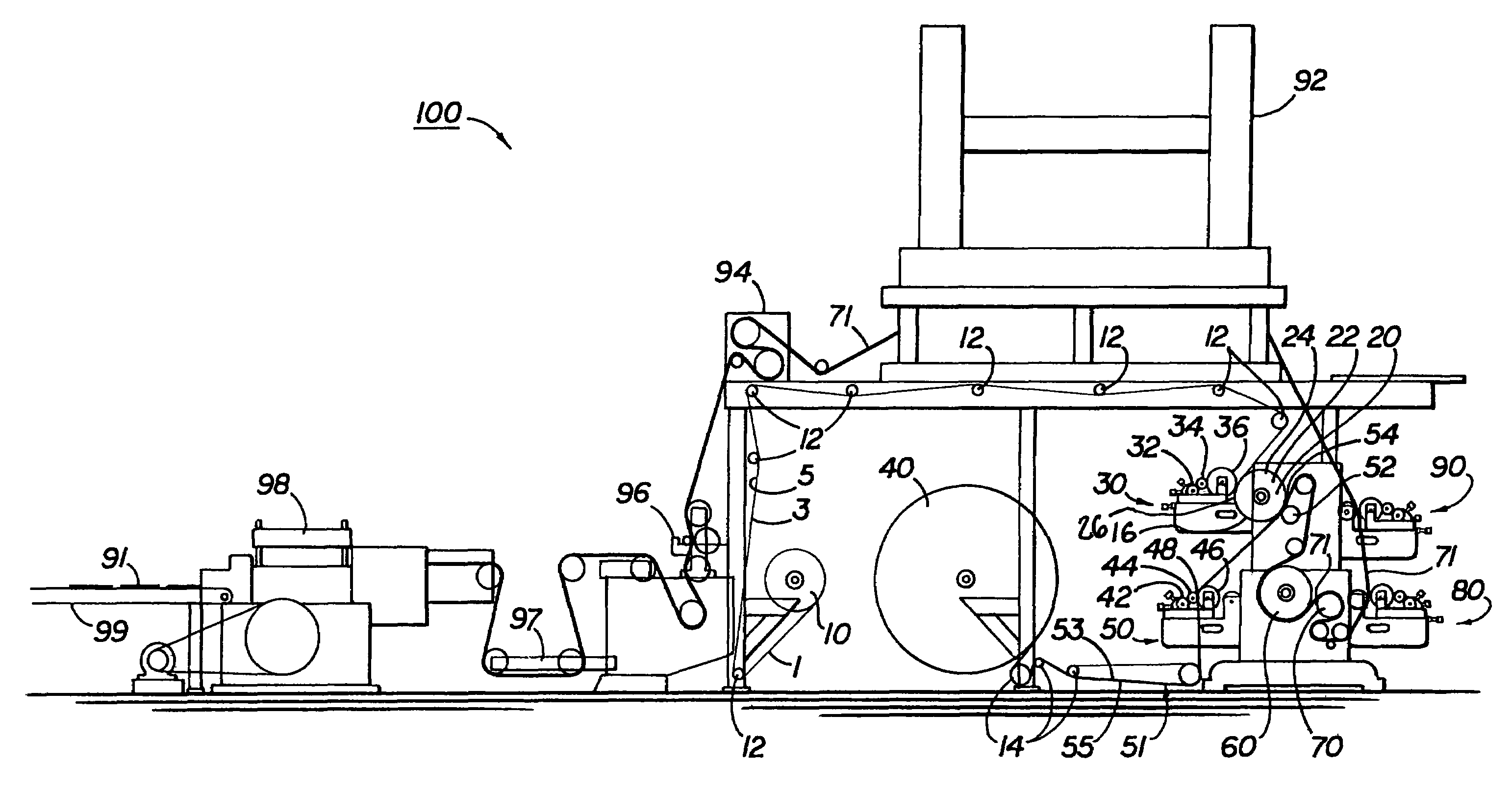
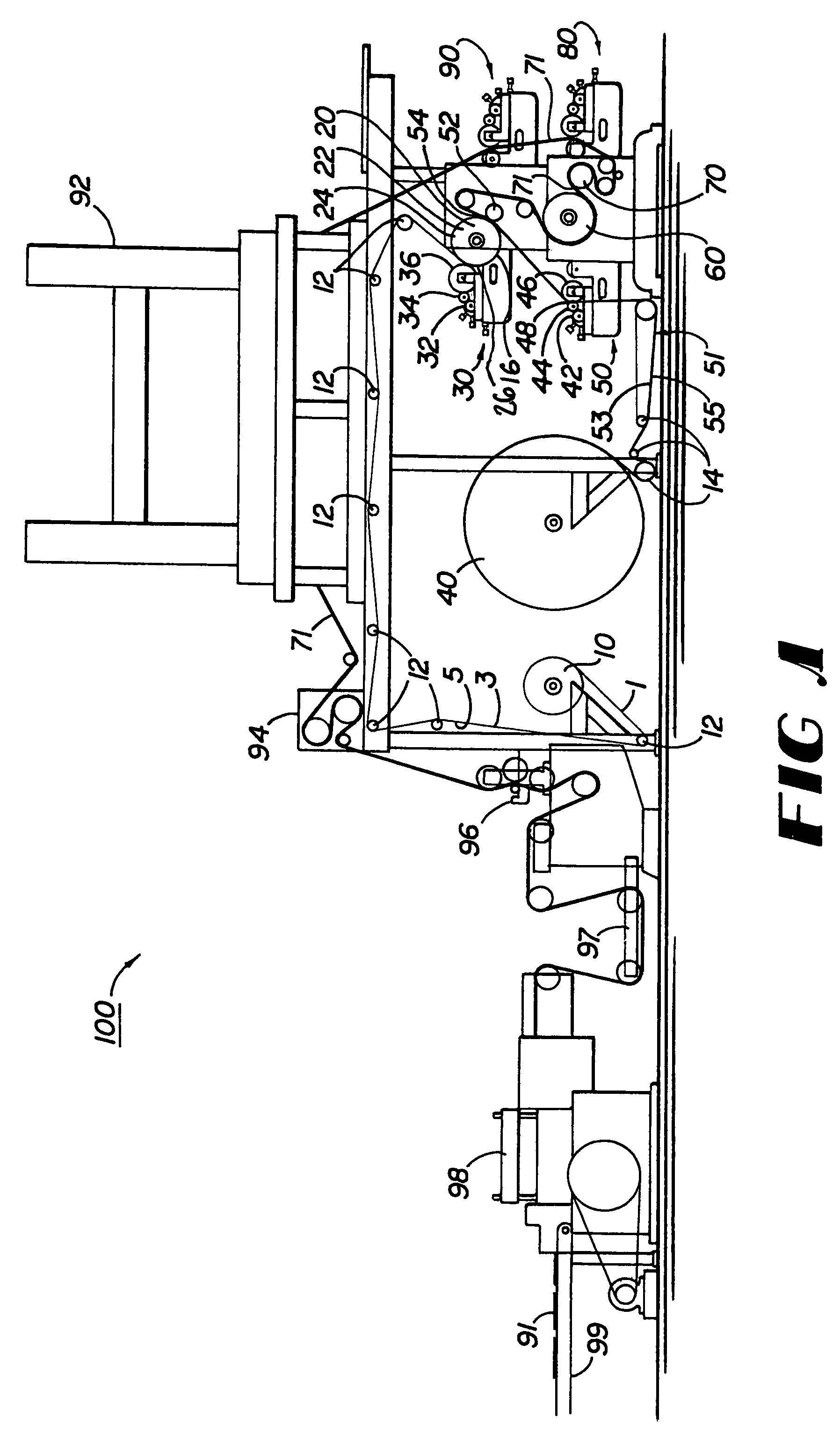
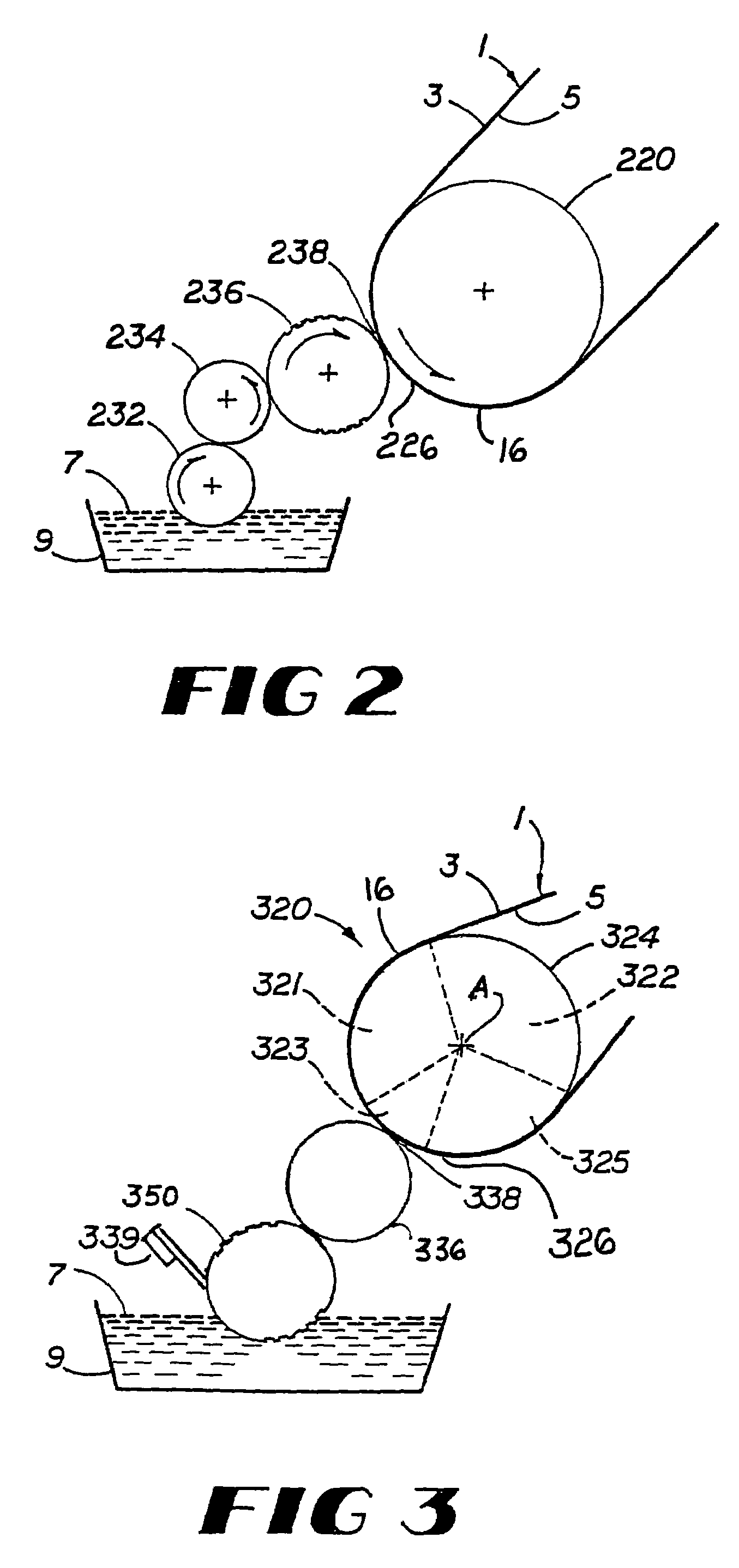
[0029]Referring in general to FIGS. 1-5, various embodiments of the system and apparatus for carrying out the method(s) of the present invention are shown. In one embodiment, in particular referring first to FIG. 1, the present invention provides a system 100 for metal removal from or demetallizing a metallized film. In the present invention, the metallized film 1 has a metallized side 3 and an opposite support side 5. For example, a...


PUM

PropertyMeasurementUnit
temperatureaaaaaaaaaa

Abstract

A system and method for at least partially demetallizing a metallized film that has a metallized side and an opposite support side. In one embodiment, the method includes rotating a heat transfer roller about an axis such that a surface of the heat transfer roller passes a heating region, a printing region and a contacting region in sequence during each rotation; heating the heat transfer roller to a first temperature; applying the film to a portion of the surface of the heated heat transfer roller with the metallized side of the film facing away from the surface of the heat transfer roller; transferring heat from the heated heat transfer roller to the film in the heating region; printing an etchant solution at a second temperature, which is lower than the first temperature, in a predetermined pattern on the metallized side of the film in the printing region, and subsequently transferring heat from the heated heat transfer roller to the film to demetallize the metallized side of the film according to the predetermined pattern in the contacting region.

Description

[0001]This present application is a divisional of U.S. application Ser. No. 10 / 300,319, filed Nov. 20, 2002, now U.S. Pat. No. 6,946,082 which claims the benefit of U.S. Provisional Application No. 60 / 331,814 filed Nov. 20, 2001, each of which is incorporated herein in its entirety.BACKGROUND OF THE INVENTION[0002]1. Field of the Invention[0003]This invention relates to an apparatus and method of at least partially demetallizing a metallized film. More particularly, this invention relates to an apparatus and method of selectively demetallizing a metallized film that utilizes a heat transfer roller to heat a metallized film prior to, during and after the application of a caustic solution.[0004]2. The Prior Art[0005]Thin metallic films are commonly used in the conversion of microwave energy, incident upon such a film, to thermal energy useful, for example, in the heating of food. It has been found that microwave energy is more efficiently converted to useful thermal energy within meta...

Claims


Application Information

Patent Timeline
Patent Type & Authority Patents(United States)
IPC IPC(8): B41F5/04B41M3/00B44C1/22C03C15/00C03C25/68C23F1/00C23F1/02C23F1/08
CPCB41M3/006C23F1/08C23F1/02
Inventor WATKINS, JEFFREY T.
Owner WATKINS JEFFREY T
Why Eureka
Try Eureka