Occupant protection device

a technology for occupant protection and occupants, which is applied in the direction of pedestrian/occupant safety arrangement, vehicular safety arrangments, vehicle components, etc., can solve the problems of relative rotation of the expanding body and the expanding body, affecting the safety of passengers, etc., so as to reduce the cost and simplify the structure

Inactive Publication Date: 2009-08-25
HONDA MOTOR CO LTD
View PDF12 Cites 23 Cited by
  • Summary
  • Abstract
  • Description
  • Claims
  • Application Information

AI Technical Summary

Benefits of technology

[0014]Since the inflator is thus provided on the side of mounting the door to the vehicle body, it is possible to shift the position of the inflator with respect to the occupant. As a result, the need to cover the inflator with a high-efficiency impact-absorbing structure is eliminated, thereby enabling a simplification of the structure. Also, since the end portion of the inflator at which the fluid delivery port is formed is directly inserted in the expanding body, it is possible to directly feed the fluid from the inflator to the expanding portion during a vehicle collision. As a result, outgassing of the fluid can be prevented. Moreover, since the inflator is provided on the side where the door is mounted to the vehicle body, the input force to the inflator by opening and closing of the door can be minimized.
[0016]Providing the inflator between the upper portion and the middle portion of the door, that is, outside the lower portion, can minimize the effects acting on the inflator during a side impact by another vehicle.
[0018]Disposing the inflator to partially overlap the expanding body in the vertical direction can increase storability by making the overall size compact.
[0020]According to this constitution, the inflator is mounted on a mounted member on the vehicle body side so as to be rotatable about an axis that follows the vertical direction. For this reason, even when the mounted member deforms during a vehicle collision to cause an input force to the inflator that can generate relative rotation with the expanding body via the mounted member, since the inflator rotates about an axis that follows the vertical direction with respect to the mounted member, relative rotation with respect to the expanding body can be controlled. Accordingly, it is possible to suppress damage during a vehicle collision even with an air bag device in which the inflator is disposed to the side of the expanding body.
[0022]According to such a constitution, the mounting members for mounting the inflator on the mounted member restrict movement of the inflator in the vertical direction with respect to the mounted member. There is therefore no need to separately provide a vertical movement restriction member, enabling simplification of the structure and a reduction in costs.

Problems solved by technology

Moreover, since the impact absorption margin (stroke) decreases by an amount corresponding to the inflator, a high-efficiency impact-absorbing configuration becomes necessary, thereby leading to complication of the structure.
As a result, a relatively large input force may occur at the inflator during opening and closing of the door.
In the case of a structure that disposes the inflator on a side of the expanding body, deformation of a mounted member on the vehicle body side to which the air bag device is mounted during a collision may cause relative rotation of the expanding body and the inflator.
This may result in damage to the member and the like that couples the expanding body and the inflator.
For example, there are numerous cases of side impacts with utility poles and trees that are long in the vertical direction.
During such impacts, the occurrence of local deformation in the mounted member increases the likelihood of the relative rotation described above.

Method used


Image

  • Occupant protection device
  • Occupant protection device
  • Occupant protection device

Examples


first embodiment

[0039]A first embodiment of the occupant protection device according to the present invention shall be described below with reference to FIGS. 1 to 9.

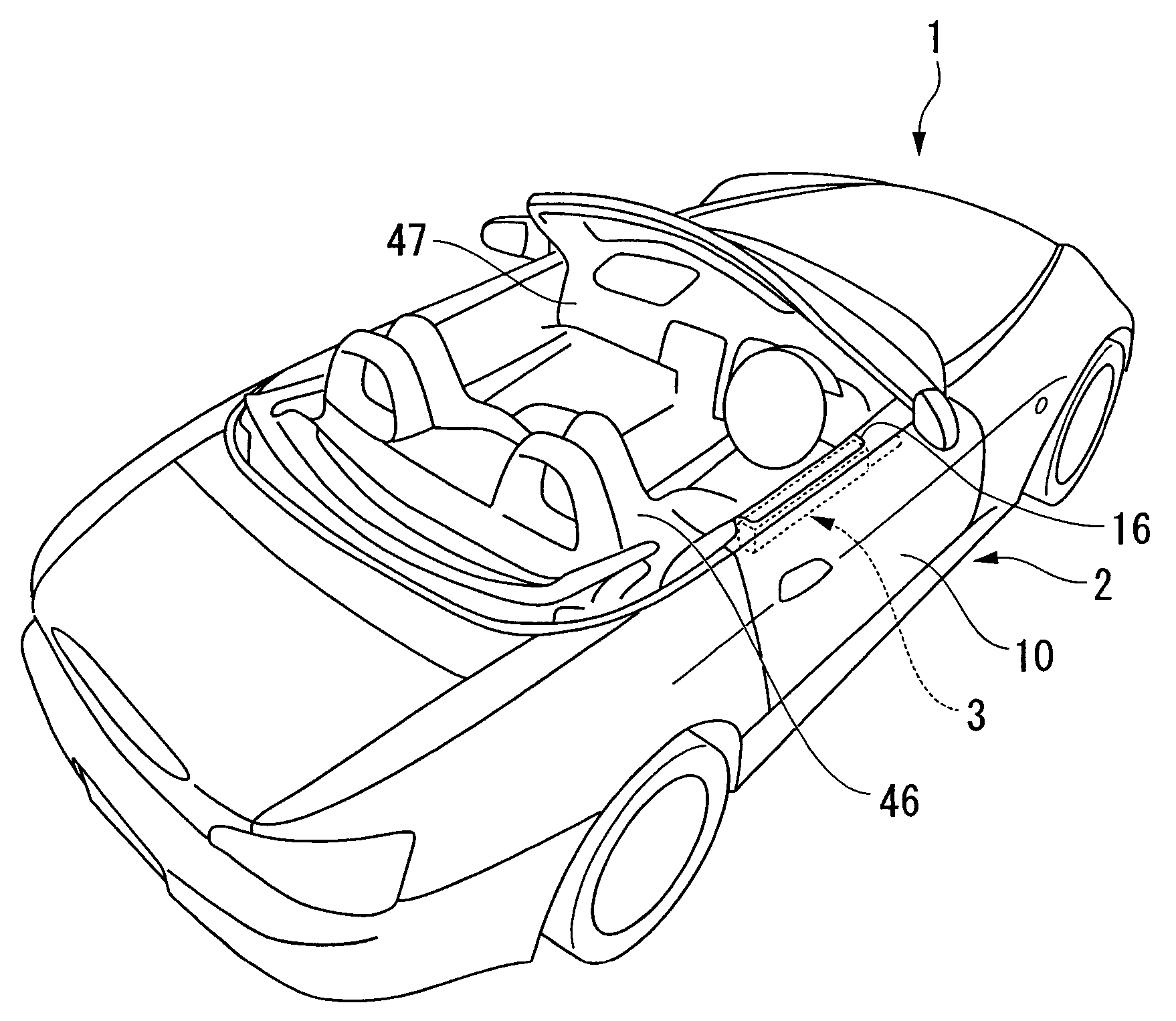
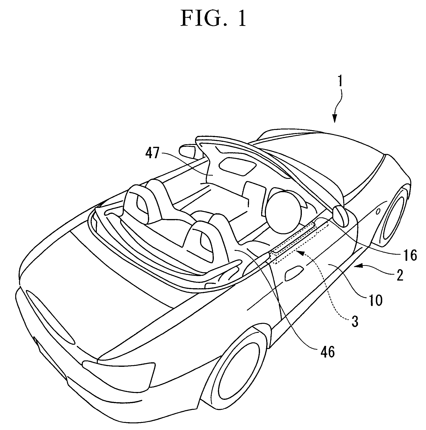
[0040]FIG. 1 shows a four-wheeled vehicle 1. The vehicle 1 is an open-roof type in which the roof is openable or detachable. An air bag device 3 is disposed as the occupant protection device of the present embodiment in a door 10 provided on the side portion of a vehicle body 2 in the vehicle 1.

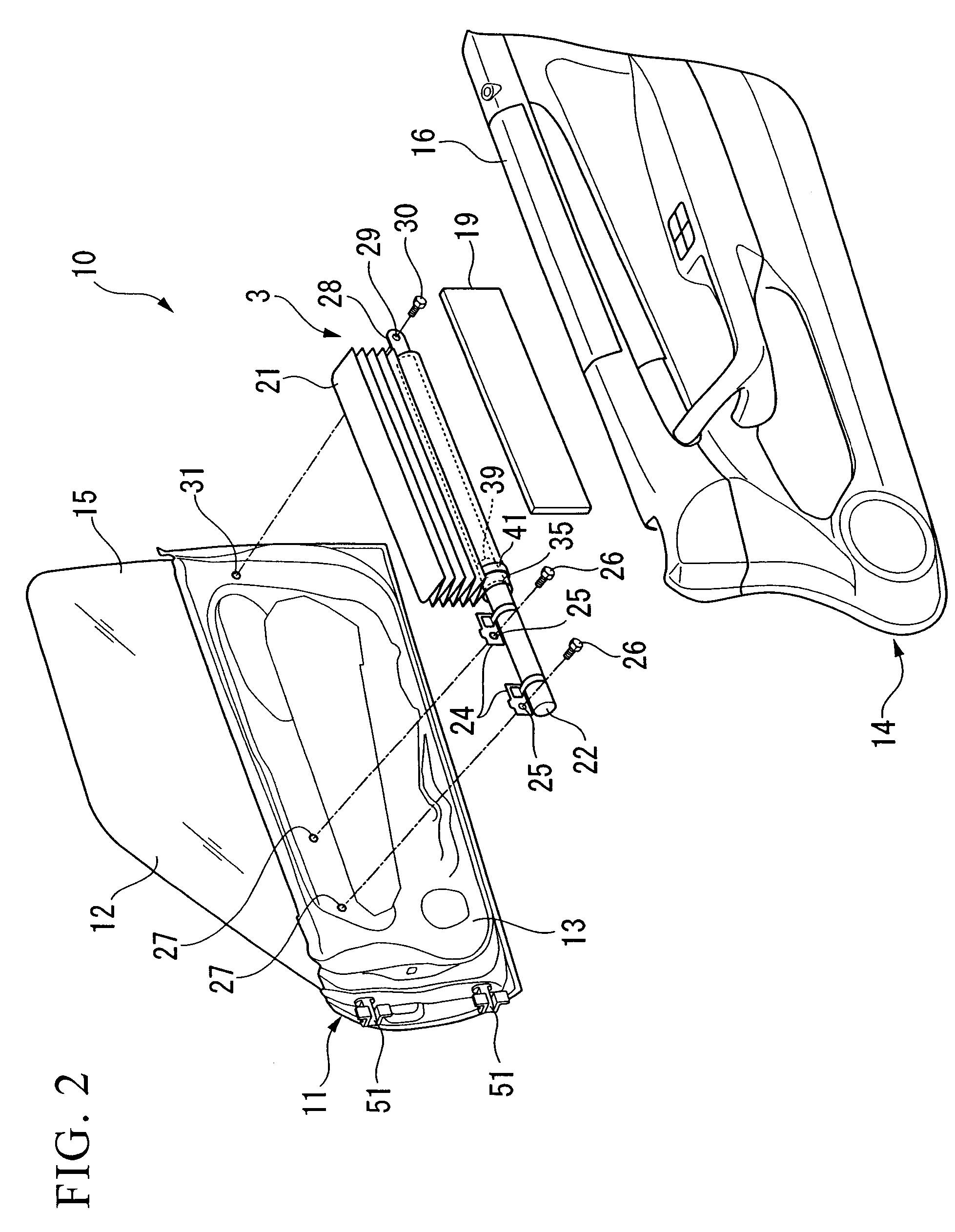
[0041]FIG. 2 is specifically an exploded perspective view of the door 10 on the right side of the vehicle, while FIG. 3 is an assembly drawing of the same. Note that in the description given below, the door 10 is in a closed state.

[0042]The door 10 has a metal door body 11, a window glass 12 that can move up and down, and a door lining 14. The door body 11 is disposed perpendicular to the vehicle width direction. The window glass 12 extends upward along the door body 11 from within the door body 11. The door lining 14 covers the cabin interior s...

second embodiment

[0057]A second embodiment of the occupant protection device according to the present invention shall next be described below with reference to FIGS. 10 to 14B.

[0058]FIG. 10 is an exploded perspective view of a door 110 on the right side of a vehicle to which an air bag device 118, serving as an occupant protection device according to the present embodiment, has been provided. FIG. 11 is an assembly drawing of the same. Here, the door 110 is one that is attached to an open-roof type vehicle in which the roof is openable or detachable. Note that in the description given below, the door 110 is in a closed state.

[0059]The door 110 has a metal door body (mounted member) 111, a window glass 112 that can move up and down, and a door lining 114. The door body 111 is disposed perpendicular to the vehicle width direction. The window glass 112 extends upward along the door body 111 from within the door body 111. The door lining 114 covers the cabin interior side of an inner panel 113 that cons...


PUM


Abstract

An occupant protection device that is provided in a door on the side of a vehicle, including an inflator that has an end portion at which a fluid delivery port is formed and delivers a fluid during a vehicle collision, and an expanding body that expands by the fluid fed by the inflator to cover the inside surface of a window provided in the door, with the end portion of the inflator being directly inserted in the expanding body, and the inflator being provided on the side of the door to be mounted to the vehicle body in the longitudinal direction of the vehicle.

Description

BACKGROUND OF THE INVENTION[0001]1. Field of the Invention[0002]The present invention relates to an occupant protection device that is provided in a vehicle door and inflates an expanding body along the inside surface of a window.[0003]Priority is claimed on Japanese Patent Application No. 2005-332575, filed Nov. 17, 2005, and Japanese Patent Application No. 2005-351779, filed Dec. 6, 2005, the content of which is incorporated herein by reference.[0004]2. Description of Related Art[0005]As an occupant protection device that is provided in a door of a vehicle, there is known a door-mounted occupant protection device that deploys an expanding body that is provided between an inner panel of the door and a lining that covers the cabin interior side thereof. Among this type of occupant protection device, in order to shorten the overall length, one has a structure in which the end portion of the inflator where a fluid delivery port is formed is directly inserted in the expanding body, wit...

Claims


Application Information

Patent Timeline
Patent Type & Authority Patents(United States)
IPC IPC(8): B60R21/16
CPCB60R21/21B60R2021/0048B60R21/23138
Inventor OCHIAI, FUMIHARUYASUHARA, FUMITOSHIKAWAMURA, TOHRUNISHIDA, YUSUKE
Owner HONDA MOTOR CO LTD
Why Eureka
Try Eureka