High-frequency module
a high-frequency module and module technology, applied in the field of high-frequency modules, can solve the problems of noise, crosstalk between the antenna terminals, deterioration of separation characteristics between the two antenna terminals, etc., and achieve excellent separation characteristics
- Summary
- Abstract
- Description
- Claims
- Application Information
AI Technical Summary
Benefits of technology
Problems solved by technology
Method used
Image
Examples
first preferred embodiment
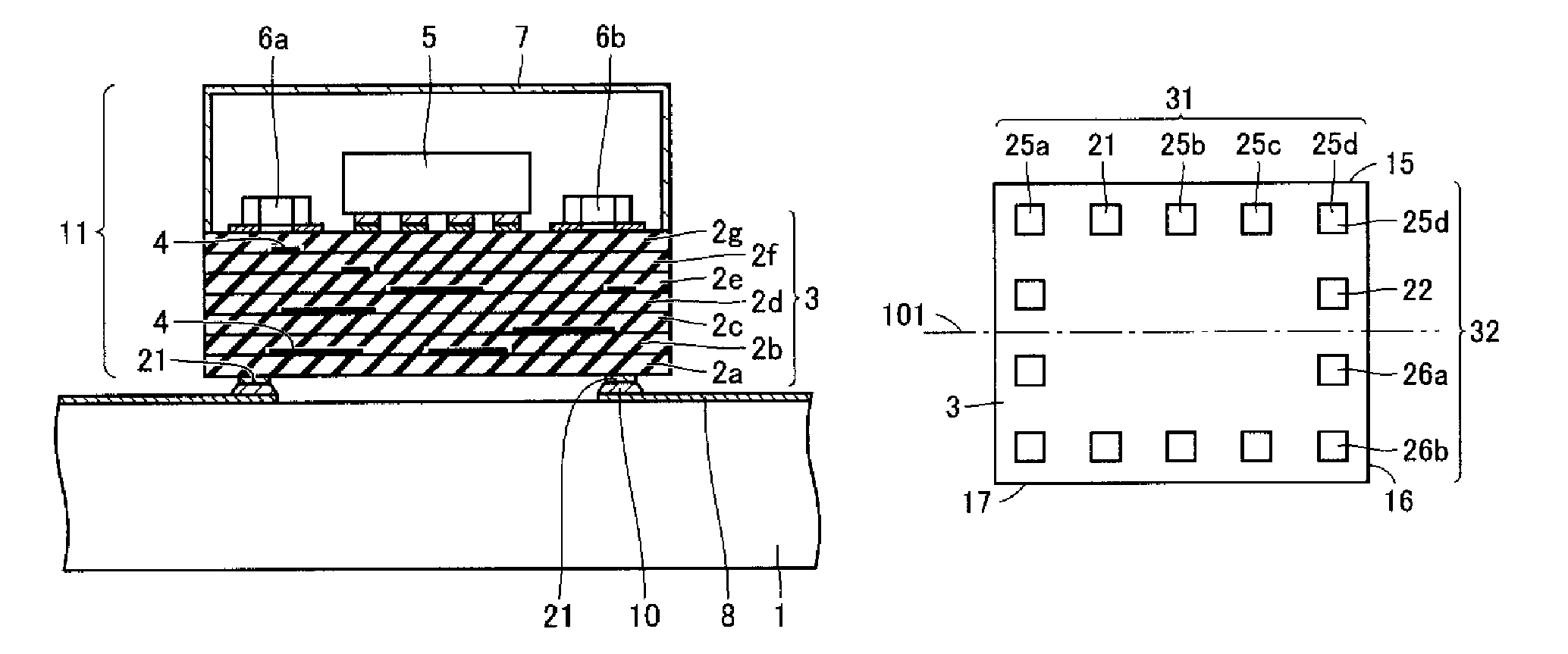
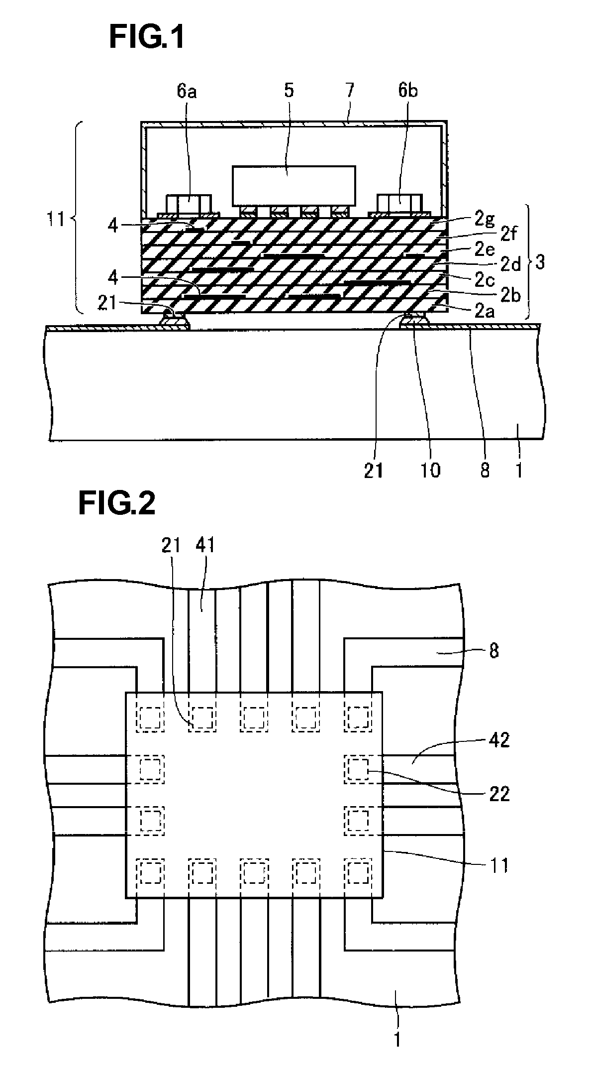
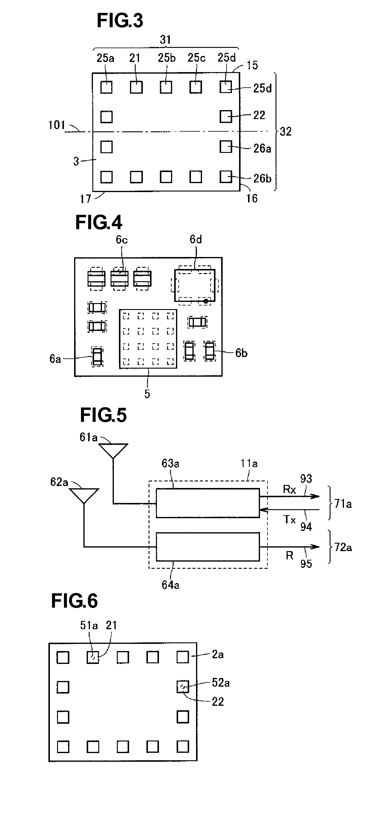
[0038]A high-frequency module according to a first preferred embodiment of the present invention is described below with reference to FIGS. 1 to 14.
[0039]FIG. 1 is a schematic illustration of a cross sectional view of the high-frequency module according to the present preferred embodiment when mounted on a module mounting substrate. FIG. 2 is a schematic illustration showing a plan view of the high-frequency module when mounted on the module mounting substrate. As shown in FIGS. 1 and 2, a plurality of terminals disposed on a first surface of a high-frequency module 11 are electrically connected to the upper surface of an wiring electrode 8 disposed on a surface of a printed circuit board 1 defining a module mounting substrate via a connecting material, such as a solder 10, for example. Thus, the high-frequency module 11 is provided.
[0040]The high-frequency module 11 includes a multilayer substrate 3 defining a body. The multilayer substrate 3 includes stacked dielectric layers 2a t...
second preferred embodiment
[0075]A high-frequency module according to a second preferred embodiment of the present invention is described below with reference to FIGS. 15 and 16.
[0076]FIG. 15 is a plan view of the high-frequency module according to the present preferred embodiment when an upper cover thereof is removed. FIG. 16 is a bottom view of the high-frequency module according to the present preferred embodiment. According to the present preferred embodiment, the high-frequency module includes a multilayer substrate 81. Two IC chips 82a and 82b and external elements 83a to 83c (such as a stacked capacitor or a stacked inductor) are disposed on the surface of the multilayer substrate 81 remote from a module mounting substrate that is connected to the multilayer substrate 81.
[0077]A plurality of terminals 86 are disposed on the bottom surface of the multilayer substrate 81. The plurality of terminals 86 include a first antenna terminal 84 and a second antenna terminal 85. The multilayer substrate 81 prefe...
third preferred embodiment
[0080]A high-frequency module according to a third preferred embodiment of the present invention is described below with reference to FIGS. 17 and 18.
[0081]FIG. 17 is a schematic illustration showing a cross-sectional view of the high-frequency module according to the present preferred embodiment. FIG. 18 is a bottom view of the high-frequency module according to the present preferred embodiment.
[0082]According to the present preferred embodiment, the high-frequency module includes a multilayer substrate 87 and external elements 82a, 83a, and 83b disposed on a surface of the multilayer substrate 87. The external element 82a is an active component (such as an IC chip). The external elements 83a and 83b are passive components (such as stacked capacitors). Additionally, the high-frequency module according to this preferred embodiment includes an outer case 91 that is arranged so as to cover the external elements 82a, 83a, and 83b.
[0083]According to the present preferred embodiment, a ...
PUM
 Abstract
Description
Claims
Application Information
 - R&D
- Intellectual Property
- Life Sciences
- Materials
- Tech Scout
- Unparalleled Data Quality
- Higher Quality Content
- 60% Fewer Hallucinations
Browse by: Latest US Patents, China's latest patents, Technical Efficacy Thesaurus, Application Domain, Technology Topic, Popular Technical Reports.
© 2025 PatSnap. All rights reserved.Legal|Privacy policy|Modern Slavery Act Transparency Statement|Sitemap|About US| Contact US: help@patsnap.com


