System and method for generating header error control byte for Asynchronous Transfer Mode cell

a header error and control byte technology, applied in the field of generating header error control byte for atm cells, can solve the problem of relatively complex process of computing the value of hec byte b>202/b> using software, and achieve the effect of efficient and fast way of generating, high flexibility, and efficient header error control byte generation

Inactive Publication Date: 2009-08-25
AVAGO TECH WIRELESS IP SINGAPORE PTE
View PDF43 Cites 6 Cited by
  • Summary
  • Abstract
  • Description
  • Claims
  • Application Information

AI Technical Summary

Benefits of technology

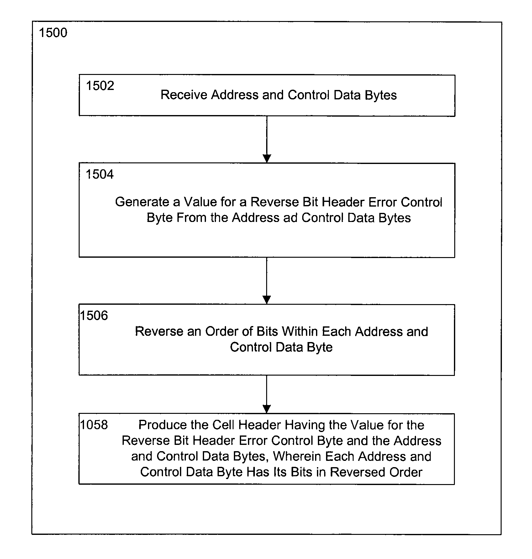
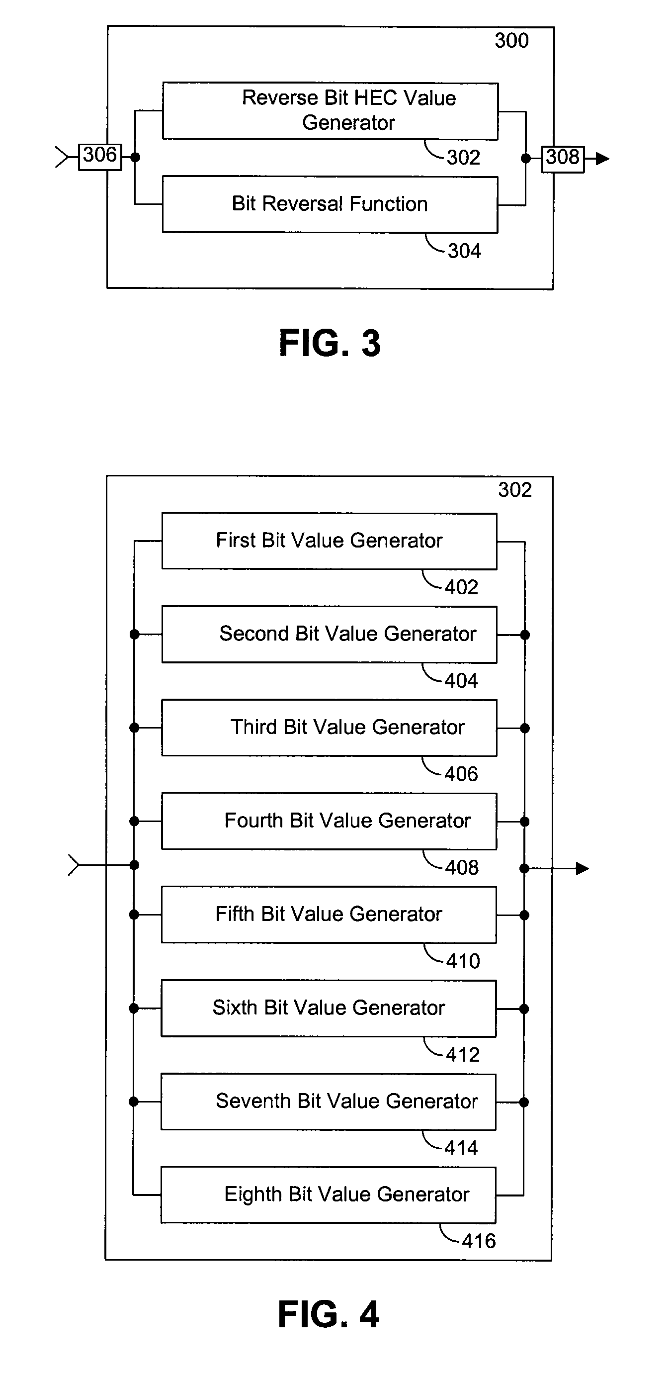
[0023]In one embodiment, the present invention provides a method and apparatus for efficiently generating a header error control byte for an ATM cell in a modem processor by providing a processor instruction for generating a header error control byte for an ATM cell. Thus, the present invention advantageously provides a processor with the ability to generate a header error control byte with a single instruction thus allowing for a more efficient and faster way of generating the HEC byte value for each ATM cell. The computed HEC byte is formatted in reverse bit order for subsequent processing within the modem. Moreover, the present invention reverses the bit-order of the ATM cell header's address and control fields for subsequent processing within the modem. Thus, the present invention also advantageously provides great flexibility in determining the arrangement and flow of data during the generating and bit-reversing process through the use of registers and memory for storing the ATM cell header's address and control bytes and the computed HEC byte.

Problems solved by technology

Unfortunately, computing the value of HEC byte 202 using software is a relatively complex process.

Method used


Image

  • System and method for generating header error control byte for Asynchronous Transfer Mode cell
  • System and method for generating header error control byte for Asynchronous Transfer Mode cell
  • System and method for generating header error control byte for Asynchronous Transfer Mode cell

Examples


Embodiment Construction

[0046]The present invention will now be described in detail with reference to a few preferred embodiments thereof as illustrated in the accompanying drawings. In the following description, numerous specific details are set forth in order to provide a thorough understanding of the present invention. It will be apparent, however, to one skilled in the art, that the present invention may be practiced without some or all of these specific details. In other instances, well known processes and steps have not been described in detail in order not to unnecessarily obscure the present invention.

[0047]The present invention relates to Asynchronous Transfer Mode (ATM) communications. The present invention can be used in an implementation of an ADSL Termination Unit—Central (Office) (ATU-C) in an ADSL system, also known as a CO modem. In an ADSL system, the rate of transmission and reception of data is asymmetrical. In general, more data is transmitted from the ATU-C to an ADSL Termination Unit—...


PUM


Abstract

In an Asynchronous Transfer Mode cell, a method and apparatus are disclosed for producing a cell header having bytes with bits in reverse order. Address and control data bytes are received, and a value for a reverse bit Header Error Control byte is generated from the address and control data bytes. Additionally, the order of bits within each address and control data byte is reversed. The produced cell header comprises the reverse bit Header Error Control byte and the address and control data bytes with each address and control data byte having its bits in reversed order. In one embodiment, the present invention provides a processor instruction for producing the cell header having bytes with bits in reverse order. The instruction receives as input address and control data bytes. The instruction then computes a Header Error Control byte and formats the Header Error Control byte in reverse bit order for subsequent processing within the modem. Additionally, the instruction also reverses the bit-order of each byte of the cell header's address and control fields for subsequent processing within the modem.

Description

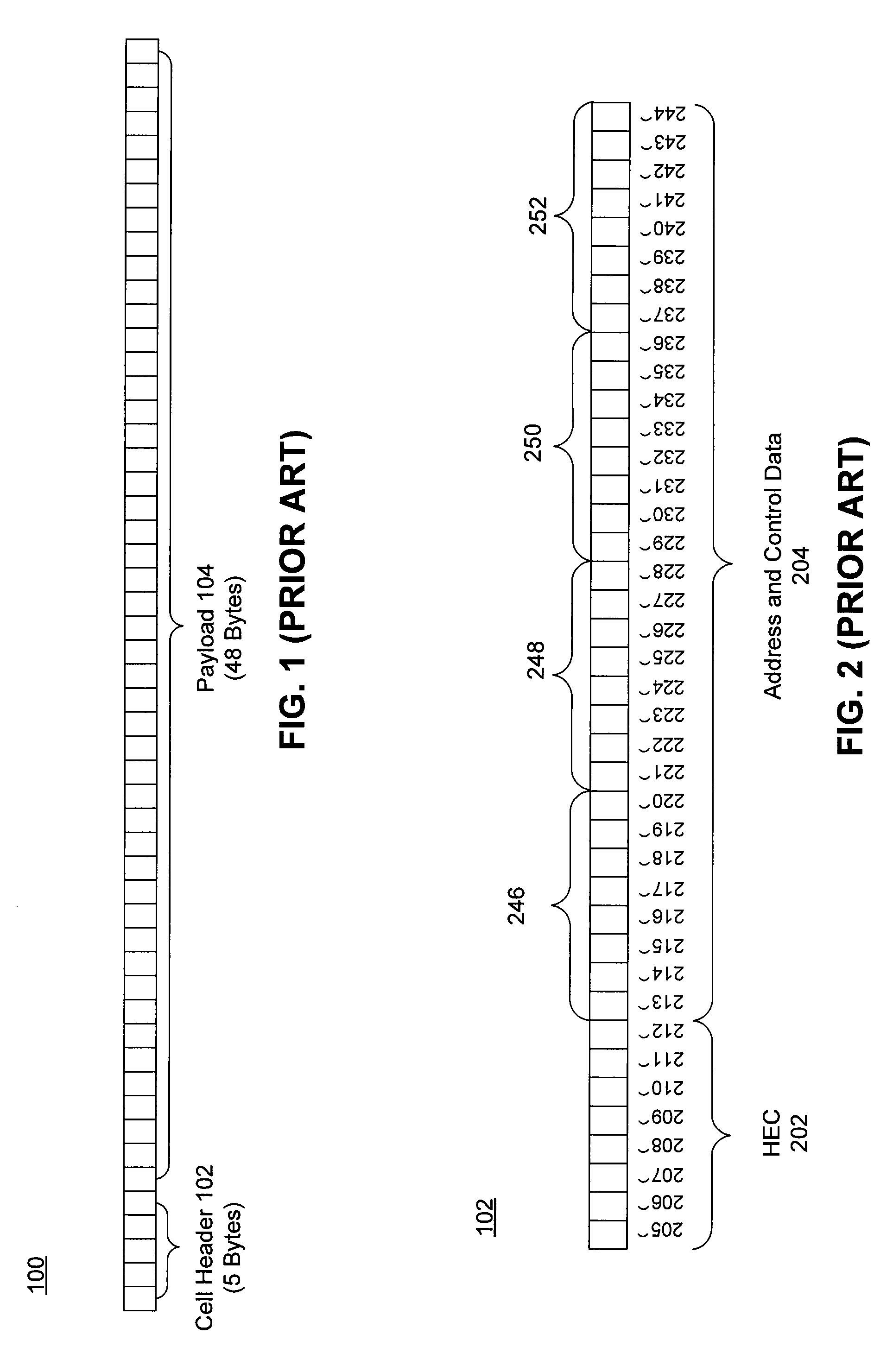
RELATED APPLICATIONS[0001]This application claims priority from U.S. provisional application Ser. No. 60 / 505,858 entitled, “System and Method for Generating Header Error Control Byte for Asynchronous Transfer Mode Cell” by Mark Taunton and Timothy Dobson and filed on Sep. 26, 2003 which is incorporated by reference herein in its entirety.FIELD OF THE INVENTION[0002]The present invention relates generally to Asynchronous Transfer Mode (ATM) systems and to the design of instructions for processors. More specifically, the present invention relates to a system, method and processor instruction for generating a header error control byte for an ATM cell.BACKGROUND OF THE INVENTION[0003]Asynchronous Transfer Mode (ATM) is a common way to format and transport data in a digital telecommunication system such as, for example, an Asymmetric Digital Subscriber Line (ADSL) link. ATM communicates data in streams of cells. An ATM cell comprises a five-byte cell header and 48 bytes of payload. The c...

Claims


Application Information

Patent Timeline
Patent Type & Authority Patents(United States)
IPC IPC(8): H04L12/56H04L12/28H04L12/64
CPCH04L12/5601H04L2012/5652H04L2012/6478H04L2012/5673H04L2012/5665
Inventor TAUNTON, MARKDOBSON, TIMOTHY MARTIN
Owner AVAGO TECH WIRELESS IP SINGAPORE PTE
Why Eureka
Try Eureka