Bandage dispenser

a bandage dispenser and dispenser technology, applied in the field of on-demand dispensers, can solve the problems of inconvenient unwrapping of conventional bandages, and achieve the effects of easy and rapid presentation of bandages, easy removal, and little preparation

Inactive Publication Date: 2009-09-01
DICKMANN ALEXANDER J
View PDF19 Cites 27 Cited by
  • Summary
  • Abstract
  • Description
  • Claims
  • Application Information

AI Technical Summary

Benefits of technology

[0007]Therefore, the objects of the present invention are: to provide a sterile bandage dispenser that easily and rapidly presents a bandage to a health care provider for application to patient such that the bandage requires little preparation by the provider before applying to the patient; to provide such a dispenser that utilizes a magazine of bandages that can be easily exchanged for a fresh magazine when empty and which maintains individual bandages sterile until needed; to provide such a dispenser having a rotating daisy wheel or magazine that has individual pie shaped compartments for each bandage and penetratable upper and lower foil covers that seal the compartments; to provide such a dispenser that has an advancer that rotates and indexes each compartment over a dispensing opening and a pusher that both directly or indirectly penetrates the covers on each compartment and discharges the bandage from the compartment through a dispensing opening to allow grasping by a health care provider; to provide such a dispenser in combination with bandages individually positioned on a stiff backing wherein the backing has a line of weakness therein that allows a provider to bend the backing and expose part of the bandage to facilitate removal of the bandage therefrom; and to provide such a dispenser that is especially easy to use, that expedites health care, that is comparatively inexpensive to produce and that is especially well suited for the intended usage thereof.

Problems solved by technology

Furthermore, the doctor, nurse or technician performing the medical procedure may have their hands at least partly occupied with vials or syringes and it is inconvenient to unwrap a conventional bandage from its sterile packaging and then apply it to the patient.

Method used


Image

  • Bandage dispenser
  • Bandage dispenser
  • Bandage dispenser

Examples


Embodiment Construction

[0019]As required, detailed embodiments of the present invention are disclosed herein; however, it is to be understood that the disclosed embodiments are merely exemplary of the invention, which may be embodied in various forms. Therefore, specific structural and functional details disclosed herein are not to be interpreted as limiting, but merely as a basis for the claims and as a representative basis for teaching one skilled in the art to variously employ the present invention in virtually any appropriately detailed structure.

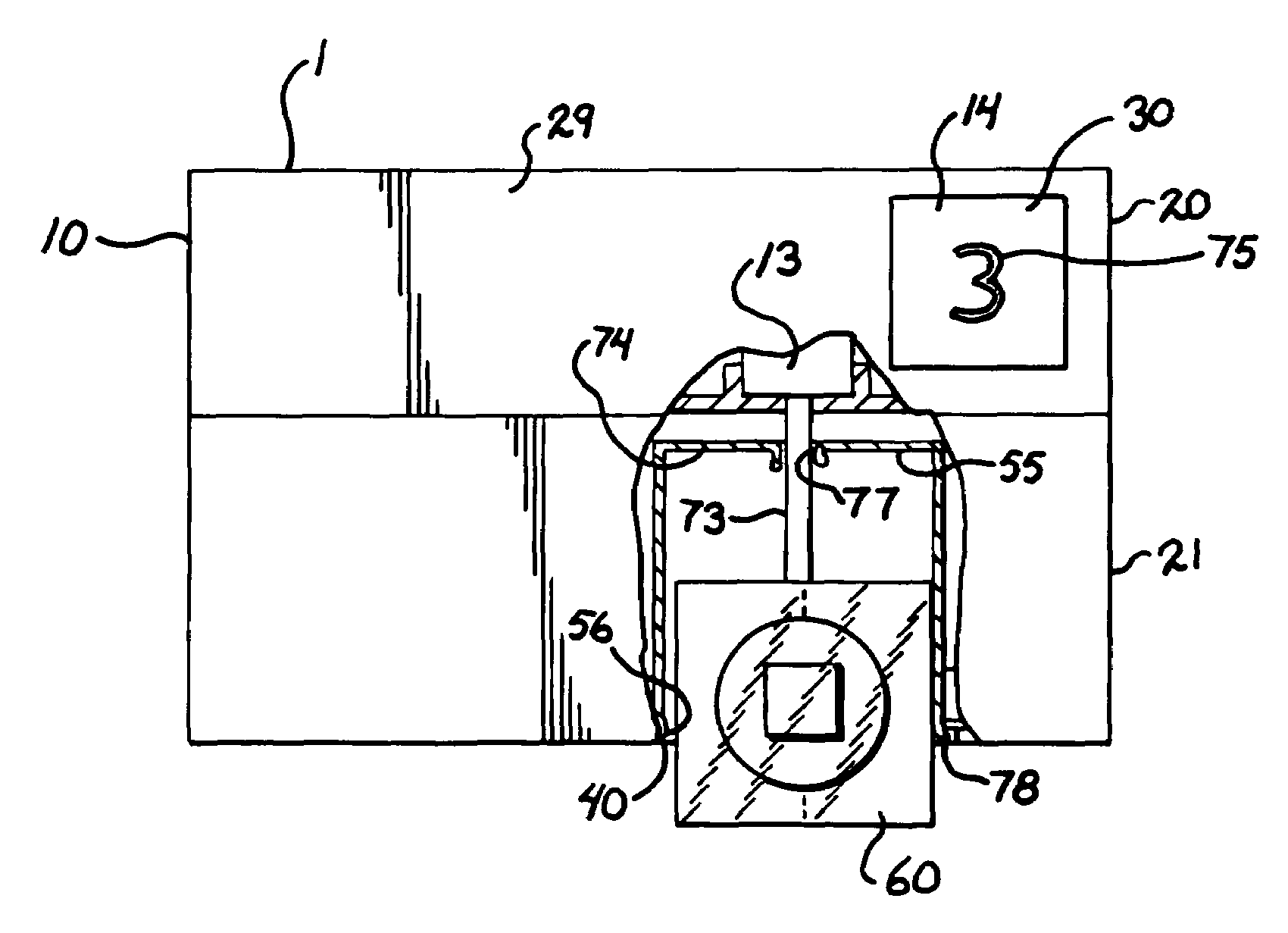
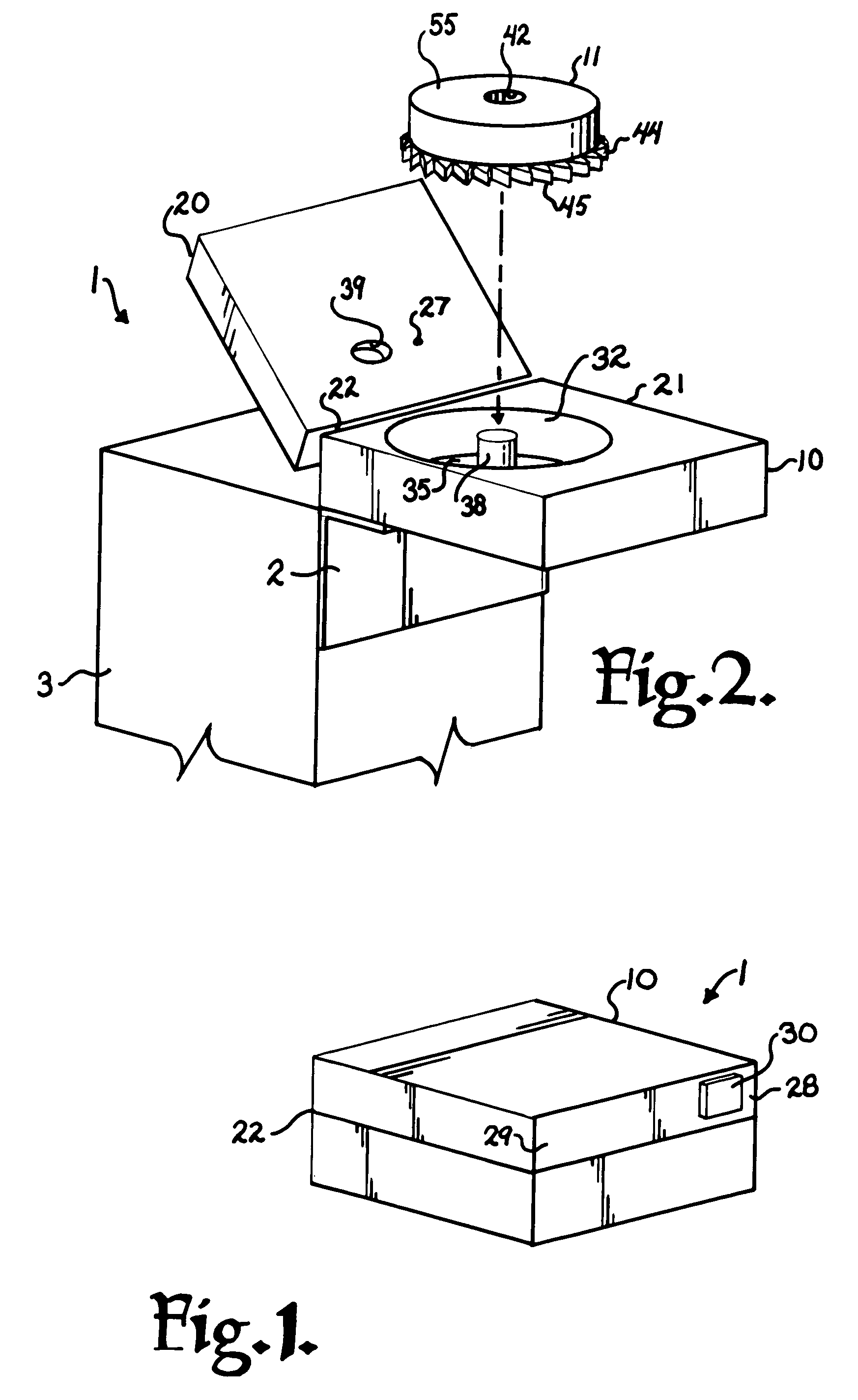
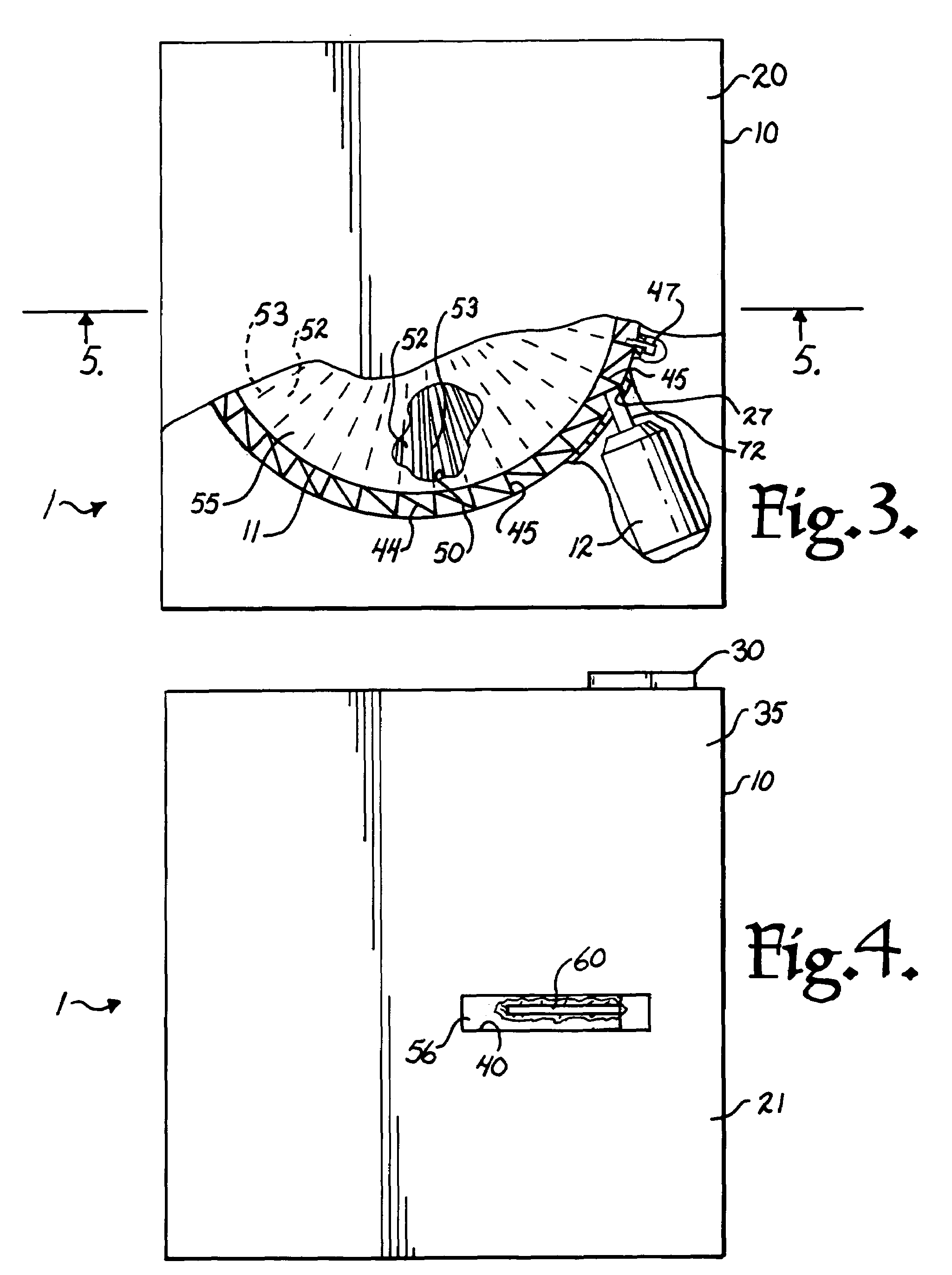
[0020]The reference numeral 1 generally indicates a bandage dispenser in accordance with the present invention mounted by a bracket 2 to a support 3. The particular structure of the support 3 is not of great importance as long as the dispenser 1 is accessible by a user and structures such as partial walls, cabinets or even independent dedicated stands can be used for the purpose.

[0021]The dispenser 1 includes a casing or housing 10, a magazine 11, an advancer...


PUM


Abstract

A bandage dispenser comprising a housing having a magazine rotatably mounted therein; an advancement assembly for rotating the magazine and a pusher mechanism. The magazine including a plurality of sterile individual pie shaped compartments each receiving a sterile bandage assembly. The pusher mechanism sequentially penetrating the compartments and ejecting the bandage assembly therefrom after each compartment is aligned with the pusher mechanism by the advancement assembly. The advancement assembly including a ratchet mechanism on the magazine and an advancement solenoid.

Description

BACKGROUND OF THE INVENTION[0001]The present application is directed to an on demand dispenser for sterile bandages and, in particular, to such a dispenser that dispenses bandages from a rotating magazine.[0002]Many medical facilities utilize a large number of bandages for covering minor punctures or wounds. For example, nurses stations that give shots, especially flu shots during the start of flu season, or the like must obtain, prepare and apply a bandage over each syringe puncture. Likewise, stations that take blood for various tests and the like must cover the resulting puncture with a bandage. Often such bandages must be applied in rapid succession. Furthermore, the doctor, nurse or technician performing the medical procedure may have their hands at least partly occupied with vials or syringes and it is inconvenient to unwrap a conventional bandage from its sterile packaging and then apply it to the patient.[0003]Therefore, it is desirable to have a dispensing apparatus that qu...

Claims


Application Information

Patent Timeline
Patent Type & Authority Patents(United States)
IPC IPC(8): G07F11/00
CPCA61F15/002A61F15/001
Inventor DICKMANN, ALEXANDER J.
Owner DICKMANN ALEXANDER J
Why Eureka
Try Eureka