Method of treating a catalytic reactor system prior to reactor servicing

a technology of catalytic reactor and reactor system, which is applied in the field of catalytic reactions, can solve the problems of increasing the fouling rate of the catalyst, the loss of overall catalyst activity, and the increase of the catalyst fouling rate, so as to reduce the servicing time

Active Publication Date: 2009-09-01
CHEVRON PHILLIPS CHEMICAL CO LP
View PDF21 Cites 31 Cited by
  • Summary
  • Abstract
  • Description
  • Claims
  • Application Information

AI Technical Summary

Benefits of technology

[0009]Also disclosed herein is a method of servicing a catalytic reactor system, comprising oxidizing the catalytic reactor system at a temperature of from about 350° F. to about 500° F. to abate at least one hazardous substance from the catalytic reactor system and reducing servicing time by about 50% of a time required for complete regenerative oxidation of the catalytic reactor system.

Problems solved by technology

However, when a new cycle is started, the starting reactor inlet temperature is typically higher than for the previous cycle (as shown by the progressively increasing reactor inlet temperature at the start of each new cycle), representing an unrestored loss in overall catalyst activity.
Furthermore, with each regeneration cycle, the fouling rate (slope) of the catalyst may increase.
Thus, regeneration of a catalytic reactor system may also increase the catalyst fouling rate, which would further reduce the total life of a catalyst.
When a shut down is necessary at a time prior to the end of a catalyst's life or one of its cycles, useable catalyst activity is lost during the regeneration.

Method used


Image

  • Method of treating a catalytic reactor system prior to reactor servicing
  • Method of treating a catalytic reactor system prior to reactor servicing
  • Method of treating a catalytic reactor system prior to reactor servicing

Examples


example

[0044]The method for servicing a catalytic reactor system by oxidizing hazardous substances having been generally described, the following example is given as a particular embodiment of the method disclosed and to demonstrate the practice and advantages thereof. It is understood that the examples are given by way of illustration and are not intended to limit the specification or the claims to follow in any manner.

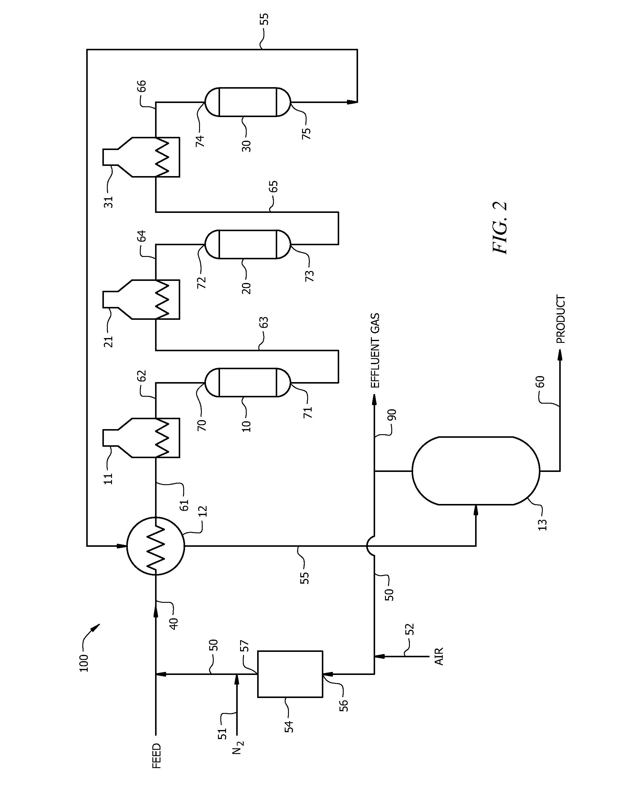
[0045]Servicing a catalytic reactor system such as the one shown in FIG. 2 to dump and screen the catalyst in the first reactor 10 and to clean several key exchangers was performed following the method described above for abating hazardous substances to safe exposure levels. A low-temperature oxidation at a maximum of about 425° F. was performed according to the procedure described in this disclosure to remove the residual hazardous substances from the catalytic reactor system and preserve the catalyst activity in the remaining cycle for its use after servicing the catalyti...


PUM

PropertyMeasurementUnit
temperatureaaaaaaaaaa
pressureaaaaaaaaaa
temperatureaaaaaaaaaa

Abstract

A method of servicing a catalytic reactor system, comprising an abatement of at least one hazardous substance from the catalytic reactor system while preserving activity of a catalyst contained therein. A method of servicing a catalytic reactor system, comprising oxidizing the catalytic reactor system at a temperature of from about 350° F. to about 500° F. to abate at least one hazardous substance from the catalytic reactor system and reducing servicing time by about 50% of a time required for complete regenerative oxidation of the catalytic reactor system. A method of servicing a catalytic reactor system, comprising abating at least one hazardous substance from the catalytic reactor system such that a fouling rate of a catalyst contained therein is substantially the same before and after the servicing.

Description

CROSS-REFERENCE TO RELATED APPLICATIONS[0001]Not Applicable.STATEMENT REGARDING FEDERALLY SPONSORED RESEARCH OR DEVELOPMENT[0002]Not applicable.REFERENCE TO A MICROFICHE APPENDIX[0003]Not applicable.FIELD OF THE INVENTION[0004]The present invention generally relates to catalytic reactions such as catalytic reforming and processing equipment associated with catalytic reforming. More specifically, the invention relates to the abatement of at least one hazardous substance from a catalytic reactor system prior to servicing of the catalytic reactor system while preserving activity of the catalyst contained therein.BACKGROUND OF THE INVENTION[0005]Catalyzed reactions and associated catalytic reactor systems are widely used in a variety of industries. A catalyst typically has a finite performance life, which may include one or more cycles of catalyst activity separated by regeneration cycles. For example, as a catalytic process continues over time, the catalyst activity generally decreases...

Claims


Application Information

Patent Timeline
Patent Type & Authority Patents(United States)
IPC IPC(8): B01D53/72B01J8/00B01J19/00B01J29/90B01J38/12B01J38/14C10G35/04
CPCB01J38/12C10G35/04B01J29/90B01J2208/02B01J38/14B01J8/00B01J19/00
Inventor GLOVA, DAVID J.CHEUNG, TIN-TACK PETERKNORR, DAN B.
Owner CHEVRON PHILLIPS CHEMICAL CO LP
Why Eureka
Try Eureka