Catalyst support substrate, method for growing carbon nanotubes using the same, and the transistor using carbon nanotubes

a technology of carbon nanotubes and support substrates, which is applied in the direction of catalyst activation/preparation, metal/metal-oxide/metal-hydroxide catalysts, etc., can solve the problems of difficult to selectively grow single-wall carbon nanotubes, difficult to deposit catalysts with desirable thicknesses on the portion, and achieve high yield and stably obtain carbon nanotubes. , the effect of high yield

Active Publication Date: 2009-09-01
NEC CORP
View PDF16 Cites 11 Cited by
  • Summary
  • Abstract
  • Description
  • Claims
  • Application Information

AI Technical Summary

Benefits of technology

[0031]Also, another object of the present invention is to improve an adhesive property of a catalyst containing film to a substrate.
[0073]In the present invention, since both of the catalyst film and the catalyst support film can be easily patterned by etching, the device of the desired shape can be formed at the good yield.

Problems solved by technology

However, in the method for using the catalyst solution as mentioned above, it is difficult to selectively grow the single-wall carbon nanotubes.
However, the case of the first method needs to use the solution which can not solve the resist, as the solvent of the catalyst solution.
Also, it was very difficult to deposit the catalyst with a desirable thickness on the portion, in which the resist of the resist pattern does not exist.
However, in this method, the edge portion of the patterned catalyst is unclear.
From this fact, it is understood that the method of using the nano-particle has the problem in the control property of the pattern formation.
However, the etching resistance of the resist is lower than the iron and the alumina.
Thus, currently, it is difficult to etch the iron and the alumina while keeping the pattern of the resist.
Moreover, in the above-mentioned first and second methods, in addition to the above-mentioned problems, the adhesive property between the catalyst support film and the substrate is not sufficiently obtained.
Hence, they have the problem that the catalyst support film is easily stripped.
However, in the techniques described in the above-mentioned gazettes, it was not always easy to obtain the sufficiently high yield.
However, in the techniques described in the above-mentioned gazettes, the foundation layer for carrying the catalyst is not designed from the viewpoint of the yield of the carbon nanotubes as mentioned above.
Thus, they did not give the useful knowledge to the technique for applying to the device, in which the carbon nanotubes are grown in a direction horizontal to the substrate, especially, to the technique for using the single-wall carbon nanotubes.
However, in this transistor, it was difficult to maintain the contact resistance between the source and drain electrodes and the carbon nanotubes at a stable low resistance.

Method used


Image

  • Catalyst support substrate, method for growing carbon nanotubes using the same, and the transistor using carbon nanotubes
  • Catalyst support substrate, method for growing carbon nanotubes using the same, and the transistor using carbon nanotubes
  • Catalyst support substrate, method for growing carbon nanotubes using the same, and the transistor using carbon nanotubes

Examples


first embodiment

[0109]The first embodiment of the present invention will be described below with reference to the attached drawings.

[0110]This embodiment relates to a method for growing the carbon nanotubes in the present invention (the method for growing the single-wall carbon nanotubes in the direction horizontal to the substrate).

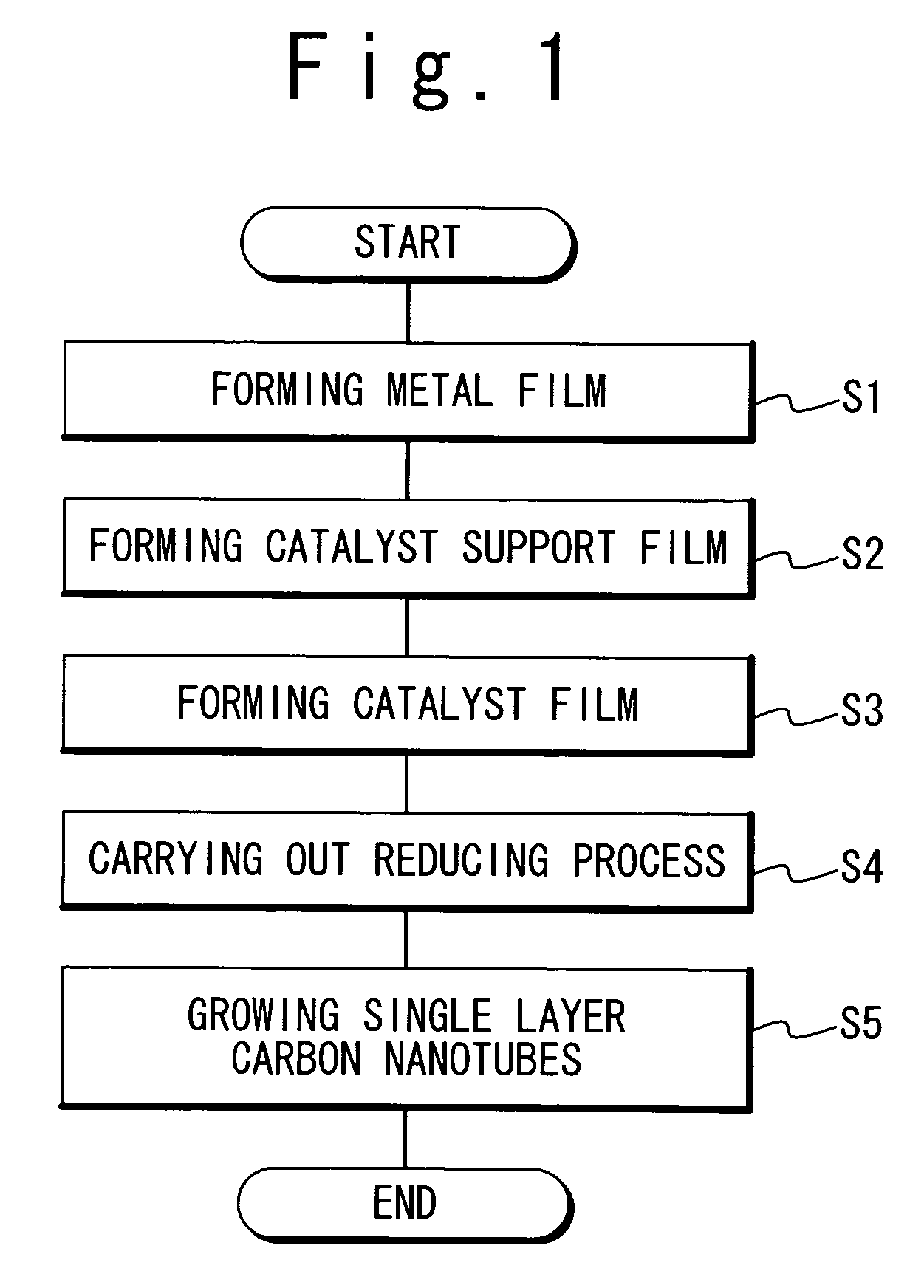
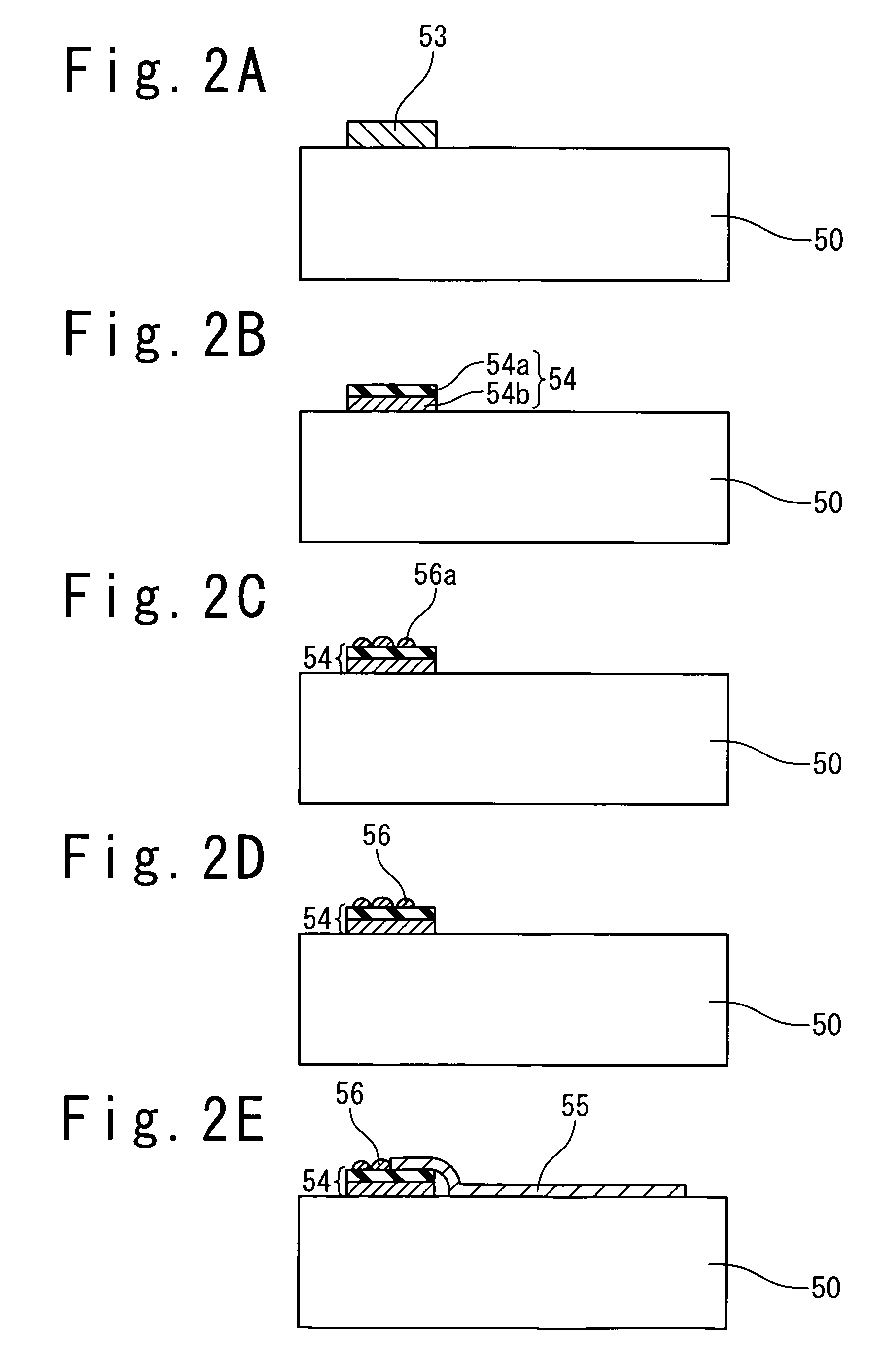
[0111]FIG. 1 is a flowchart showing a film forming process of the method for growing the carbon nanotubes in the first embodiment of the present invention. At first, the metal film composed of a first metal is formed on a substrate (Step S1). After that, the surface is oxidized or hydroxylated to form the catalyst support film including the metal oxide or metal hydroxide (Step S2). Next, the catalyst film including a second metal or the compound of that metal is formed on this catalyst support film surface (Step S3). In succession, reducing gas is brought into contact with the substrate surface including the catalyst film, and a reducing process is carried out (Step S4)...

second embodiment

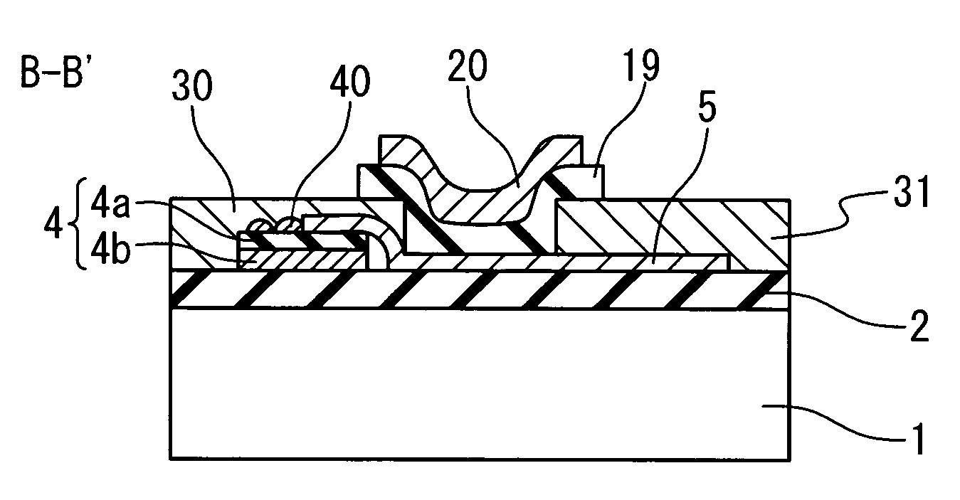
[0136]The second embodiment of the present invention will be described below with reference to the attached drawings. This embodiment relates to the transistor using the carbon nanotubes in the present invention.

[0137]FIG. 3A and FIG. 3B are views showing one example of the structure of the transistor using the carbon nanotubes in the second embodiment of the present invention. FIG. 3B shows a top view of the transistor. FIG. 3A shows a sectional view along the line AA′ of FIG. 3B. The transistor in this embodiment has the structure that a silicon oxide film 2 is formed on a silicon substrate 1, and a device portion is formed thereon. The device portion includes: a gate electrode composed of an insulating film 19 and a gate metal film 20; a source electrode 30 and a drain electrode 31 which are formed on both sides thereof; and a carbon nanotubes 5 for connecting them. The carbon nanotubes 5 are grown in the direction parallel to the substrate surface from a catalyst film 40 formed ...

first example

[0160]This example shows an example in which the boehmite is used for the material of the catalyst support film, the iron is used for the material of the catalyst film, and the single-wall carbon nanotubes are grown on the substrate. At first, aluminum of 20 nm is deposited on the silicon substrate. After that, this is heated in water boiled at 100° C. for about 30 minutes. As a result, the aluminum is changed into aluminum hydroxide oxide (another name of boehmite). Moreover, it is heated at 600° C. in air for one hour, and converted into the γ alumina, and this is used as the catalyst support film. After that, the iron of 2 nm is deposited on the γ alumina and used as the catalyst.

[0161]This sample is inserted into an electric furnace having a diameter of about 2 inches and heated up to 800° C. in argon atmosphere. At the stage of the arrival at 800° C., the atmosphere gas is switched from the argon to methane (99.999%) and kept for five minutes. After that, it is again switched t...


PUM

PropertyMeasurementUnit
temperatureaaaaaaaaaa

Abstract

A catalyst supporting substrate includes a first region (54) which is formed on a substrate (50); and a second region (55) which is formed covering a part of the first region. The first region (54) includes a catalyst supporting portion (54a) containing a first material. The second region (55) includes a catalyst portion (55) containing a second material which is different from the first material. The first material includes a metal containing at least one of elements selected from the second group to the fourteenth group of the periodic table or a compound thereof. The second material is a catalyst which grows carbon nanotubes in a vapor phase.

Description

TECHNICAL FIELD[0001]The present invention relates to a catalyst support substrate, and a method for growing carbon nanotubes using the same, and a transistor using carbon nanotubesBACKGROUND ART[0002]As a method for manufacturing single-wall carbon nanotubes with high quality, a chemical vapor deposition (CVD) method is expected to be a promising technique. This is because the control of catalyst exhibits the possibility of being able to control the growth of the single-wall carbon nanotubes.[0003]Typically, manufacturing the single-wall carbon nanotubes requires the catalyst metal, such as iron, cobalt and nickel in addition to a carbon material. In the method for manufacturing the single-wall carbon nanotubes based on a conventional vapor phase growth, the nano-particle (fine particle) of metallic oxide such as alumina or silica, or the material having porosity structure such as zeolite is used as the support of the catalyst. This support together with the salt such as the salt o...

Claims


Application Information

Patent Timeline
Patent Type & Authority Patents(United States)
IPC IPC(8): H01L51/40C01B31/02B01J21/04B01J21/06B01J23/16B01J23/46B01J23/70B01J23/745B01J35/00B01J37/00B01J37/02C23C14/14C23C16/06H01L29/786H01L51/00
CPCB01J21/063B01J23/16B01J23/46B01J23/70B01J23/745B01J37/0018B01J37/024B82Y10/00B82Y30/00B82Y40/00C01B31/0233B01J21/04H01L51/0052B01J35/0006C01B2202/02H01L51/0048B01J21/06Y10S977/742Y10S977/75Y10S438/903C01B32/162H10K85/221H10K85/615
Inventor HONGO, HIROO
Owner NEC CORP
Why Eureka
Try Eureka