
ATM communication system and ATM communication method

a communication system and atm technology, applied in the field of atm (asynchronous transmission mode) communication system, can solve the problems of inconvenient home use, complicated operation, and high cost of atm communication apparatus, and achieve the effect of convenient operation and inexpensiveness

Inactive Publication Date: 2009-09-01
KK TOSHIBA
View PDF19 Cites 29 Cited by
  • Summary
  • Abstract
  • Description
  • Claims
  • Application Information

AI Technical Summary

Benefits of technology

The present invention provides an ATM communication system and method that is inexpensive, easy to operate, and can flexibly cope with future information sources / services. The system includes a port tag adding section for identifying connection ports of information apparatuses as cell sources to ATM cells, a cell drop section for dropping cells, a cell counter for counting the number of cells, and a cell inserting section for inserting cells. The system can be easily synchronized with an external network and can be constructed using existing systems such as a PCI bus. The invention also provides an arbiter for prioritizing bus requests and guaranteeing quality of service. Overall, the invention provides an efficient and flexible solution for introducing ATM cells into a network.

Problems solved by technology

For this reason, these apparatuses are expensive.
In addition, since the conventional ATM communication apparatuses are designed on the assumption that they are maintained and operated by experts, they require complicated operations.
For this reason, the conventional ATM communication apparatuses are not suitable for home use without any modification.
The implementation of this function, therefore, becomes increasingly complicated as the transmission rates of information from information sources vary.
That is, P1394 cannot cope with various types of existing / novel information sources / information services at a low cost.
As described above, since the conventional ATM communication apparatuses are expensive and require complicated operations, they are not suitable for home use.
In addition, the conventional communication apparatuses desired for home use cannot cope with various types of existing / novel information sources / information services in the future.

Method used


Image

  • ATM communication system and ATM communication method
  • ATM communication system and ATM communication method
  • ATM communication system and ATM communication method

Examples


Embodiment Construction

[0040]An embodiment of the present invention will be described below with reference to the accompanying drawings.

1. Overall Arrangement of Private Area Network

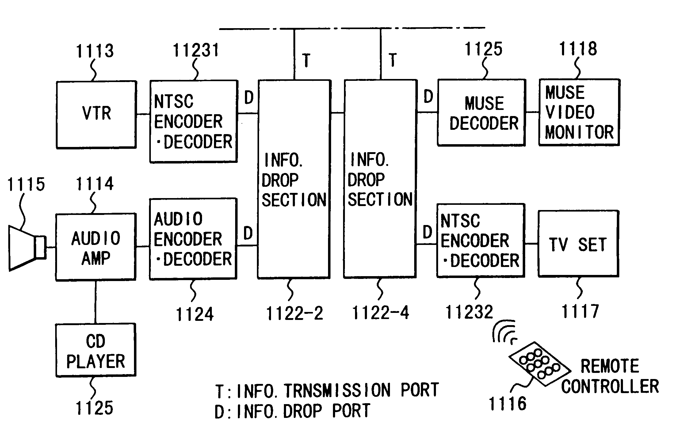
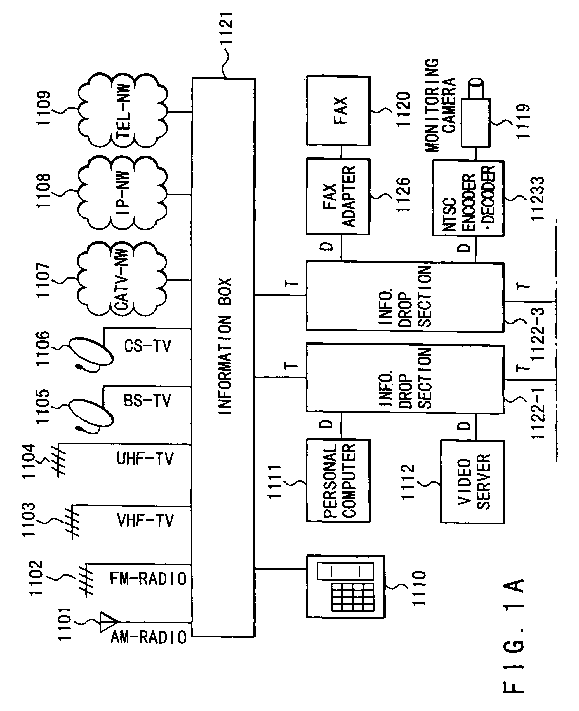
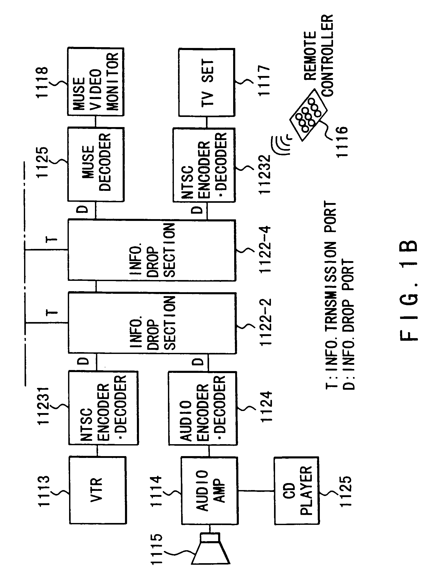
[0041]FIGS. 1A and 1B show a private area network to which the ATM communication system of the present invention is applied, and more specifically, an example of the overall arrangement of a private area network constructed in a home (to be referred to as a home network hereinafter). Home networks provide inexpensive real-time multi-rate communication services for information sources and home audio•visual•information apparatuses (to be abbreviated as AVI apparatuses hereinafter) which have or will come into widespread use in homes. Referring to FIGS. 1A and 1B, an information box 1121 and a plurality of (e.g., four in FIGS. 1A and 1B) information drop sections 1122-i (1122-1, 1122-2, . . . , 1122-4) constitute the ATM communication system of the present invention.

[0042]Referring to FIGS. 1A and 1B, as radio system services usi...


PUM


Abstract

An ATM cell transmission route is formed by hierarchically connecting a plurality of buses for connecting at least one first device and a plurality of second devices, and an ATM cell is to be transmitted from a first device designed to transmit / receive ATM cells and connected to one of the plurality of buses. The first device generates an ATM cell transmission message by inserting the ATM cell into a message in a format depending on the bus, and outputs an address for designating a device as the destination of the ATM cell transmission message by using a bus identifier for identifying one of the plurality of buses and a device identifier for identifying one of the plurality of devices. The ATM cell transmission message is then written in the device designated by the address. With this operation, an ATM communication system having a simple arrangement can be provided. In addition, ATM communication can be performed, with the QOS (quality of service) being guaranteed by priority control of an arbiter connected to one of the plurality of buses.

Description

CROSS-REFERENCE TO RELATED APPLICATIONS[0001]The present application is a continuation of U.S. application Ser. No. 09 / 703,790 filed on Nov. 2, 2000, now abandoned which is a divisional of U.S. application Ser. No. 08 / 870,425 filed on May 28, 1997, now U.S. Pat. No. 6,157,645 the entire contents each of which are hereby incorporated herein by reference, and in turn claims priority to JP 8-133090 filed on May 28, 1996.BACKGROUND OF THE INVENTION[0002]The present invention relates to an ATM (Asynchronous Transmission Mode) communication system and, more particularly, to an ATM communication system designed to be used in a private area.[0003]In recent years, ATM techniques have been vigorously studied and developed to realize a B-ISDN. As for public networks, public network ATM switching units and ATM cross-connections have been vigorously developed. The carriers in various countries have gradually been constructing ATM networks by using such ATM switching units and ATM cross-connectio...

Claims


Application Information

Patent Timeline
Patent Type & Authority Patents(United States)
IPC IPC(8): H04L12/28H04L12/56H04Q11/04
CPCH04Q11/0478H04L2012/5616H04L2012/5679H04L2012/5664
Inventor SHOBATAKE, YASURO
Owner KK TOSHIBA
Learn More