
Image processing based on direction of gravity

a technology of image processing and direction of gravity, applied in the field of image processing, can solve the problems of inability to achieve general use at reducing perspective distortion, lack of modern digital camera features, and high cost of view cameras, etc., to achieve good sharpness, improve digital image, and reduce perspective distortion

Active Publication Date: 2009-09-01
MONUMENT PEAK VENTURES LLC
View PDF14 Cites 49 Cited by
  • Summary
  • Abstract
  • Description
  • Claims
  • Application Information

AI Technical Summary

Benefits of technology

[0017]digital images are modified to generate improved digital image with reduced perspective distortion or unintentional camera rotation;

Problems solved by technology

View cameras are expensive and complex due to the many moving parts.
In addition, traditional view cameras use film and lack many of the features of modern digital cameras.
This arrangement would not be practical for general use at reducing perspective distortion.
Their video camera cannot reduce perspective distortion.
This camera cannot reduce perspective distortion in the image.
GPS and geomagnetism measuring devices are expensive.
In addition, camera requires determining the three-dimensional position of the subject, which is often difficult or impossible when the subject is inaccessible.

Method used


Image

  • Image processing based on direction of gravity
  • Image processing based on direction of gravity
  • Image processing based on direction of gravity

Examples


Embodiment Construction

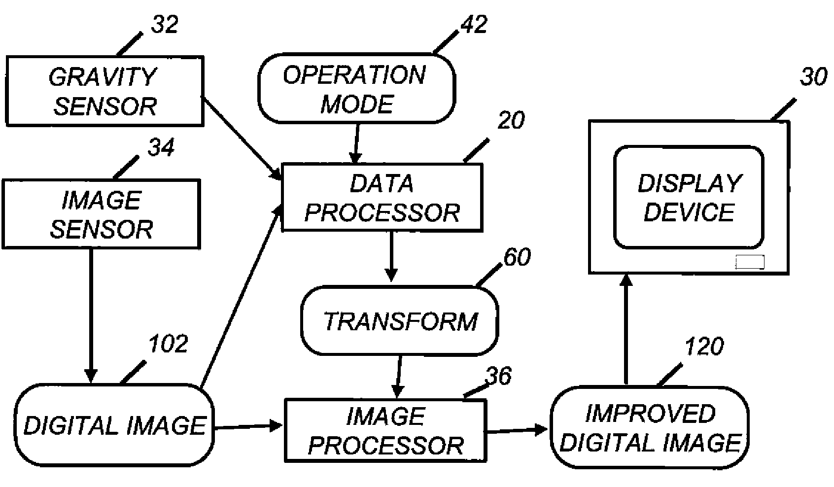
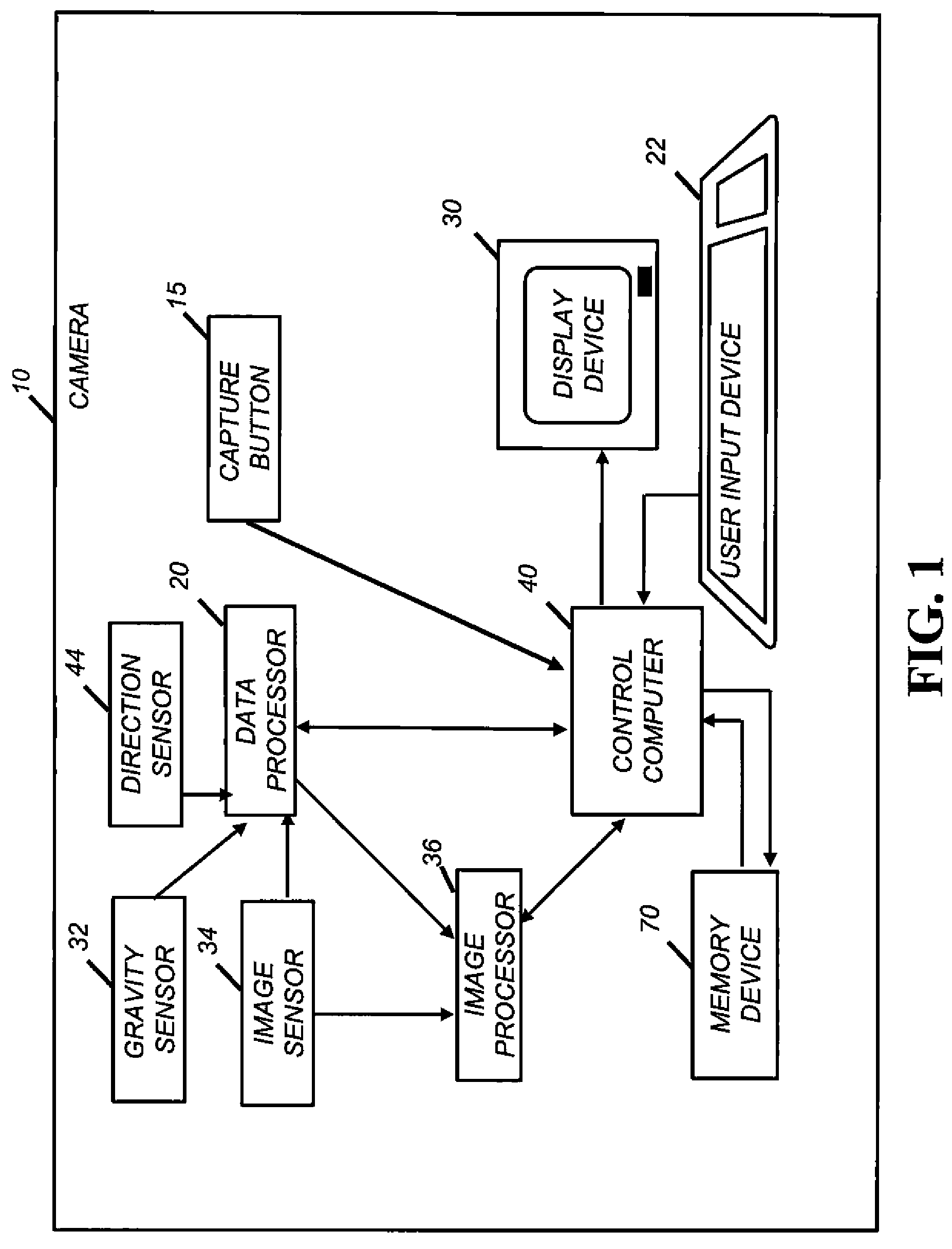
[0028]FIG. 1 shows the inventive digital camera 10. The camera includes user inputs 22. As shown, the user inputs 22 are buttons, but the user inputs could also be a joystick, touch screen, or the like. The user uses the user inputs 22 to command the operation of the camera 10, for example by selecting a mode of operation of the camera 10. The camera 10 also includes a display device 30 upon which the user can preview images captured by the camera 10 when a capture button 15 is depressed. The display device 30 is also used with the user inputs 22 so that the user can navigate through menus. The display device 30 can be, for example, a LCD or OLED screen, as are commonly used on digital cameras. The menus allow the user to select the preferences for the camera's operation. The camera can capture either still images or image in rapid succession such as a video stream.

[0029]A general control computer 40 shown in FIG. 1 can store the present invention as a computer program stored in a c...


PUM


Abstract

A method of processing a digital image to produce an improved digital image, includes receiving the digital image captured with a camera; determining a first vanishing point associated with the digital image; determining a second vanishing point associated with the digital image corresponding to a direction orthogonal the first vanishing point; determining a transform for modifying the digital image based on the first vanishing point and the second vanishing point; and applying the transform to the digital image to produce an improved digital image.

Description

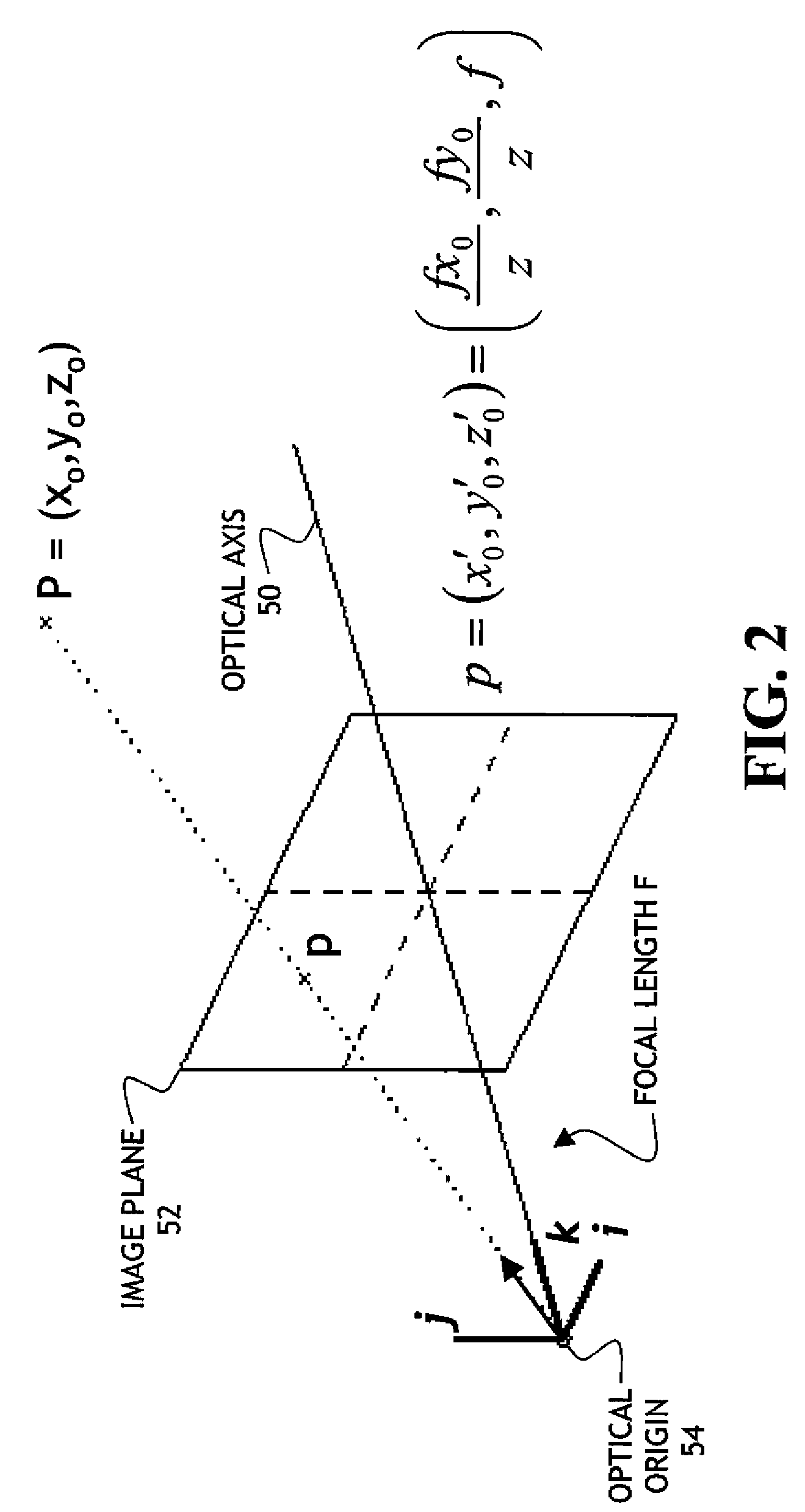
CROSS REFERENCE TO RELATED APPLICATIONS[0001]Reference is made to commonly assigned U.S. patent application Ser. No. 09 / 663,056 filed Sep. 15, 2000, entitled “A Method of Estimating and Correcting Camera Rotation With Vanishing Point Location, and U.S. patent application Ser. No. 10 / 963,344 filed concurrently herewith, entitled “Image Processing Based on Direction of Gravity” by Andrew C. Gallagher, the disclosures of which are incorporated herein.FIELD OF INVENTION[0002]The present invention relates to image processing of digital images captured by a digital camera based on the direction of gravity.BACKGROUND OF THE INVENTION[0003]Most consumer cameras are designed such that the lens and image sensors are parallel, and their centers fall on a line orthogonal to the image sensor. This arrangement generally produces good photographic results. However, due to perspective projection, parallel lines in the scene can appear to converge in the image. This phenomena is known as perspective...

Claims


Application Information

Patent Timeline
Patent Type & Authority Patents(United States)
IPC IPC(8): G06K9/32G06T15/10G06K9/36
CPCG06T5/006G06T7/004H04N5/2628H04N5/2327H04N5/2353H04N5/23248G06T7/70H04N23/68H04N23/684H04N23/73
Inventor GALLAGHER, ANDREW C.
Owner MONUMENT PEAK VENTURES LLC
Learn More