Collision object protection device

a protection device and object technology, applied in the direction of pedestrian/occupant safety arrangement, roof, tractors, etc., can solve the problems of air bag disadvantageously moving off from the predetermined position, inability to inflated and expand air bags, and difficulty in stably positioning air bags to a predetermined position, etc., to achieve sufficient rigidity (stiffness), and reliably prevent the flapping of the pillar portion

Inactive Publication Date: 2009-09-08
HONDA MOTOR CO LTD
View PDF28 Cites 46 Cited by
  • Summary
  • Abstract
  • Description
  • Claims
  • Application Information

AI Technical Summary

Benefits of technology

[0009]In this collision object protection device, after the main body portion expands to have a sufficient rigidity (stiffness), the pillar base portions and the pillar portions expand. Alternatively, after the main body portion and the pillar base portions expand to have a sufficient rigidity (stiffness), the pillar portions expand. Therefore, since the pillar portions expand after the main body portion has a sufficient rigidity, it is possible to prevent flapping of the pillar portions during the expansion of the air bag.
[0022]According to these collision object protection devices, when the air bag discharges the gas from the vent holes in the direction opposite to the vehicle body, the flows of the gas urge the pillar portions toward the vehicle body. Therefore, flapping of the pillar portions can be more reliably prevented, which enables the air bag to more stably cover the intended protection area.

Problems solved by technology

However, in the conventional collision object protection device, when the inflator injects the gas into the main body portion of the air bag which is folded back and housed to inflate and expand the air bag on the front windshield glass of the vehicle, the pillar base portions or the pillar portions often expand before the main body portion sufficiently expands.
As a result, flapping causes on a part of the pillar portion during the expansion of the air bag.
This leads to a difficulty in stably positioning the air bag to a predetermined position.
Due to this state, if the air bag is subject to a crosswind or the like, the air bag is disadvantageously moved off from the predetermined position.
In other words, according to the conventional collision object protection device, it is not possible for the inflated and expanded air bag to stably cover the intended protection area.

Method used


Image

  • Collision object protection device
  • Collision object protection device
  • Collision object protection device

Examples


first embodiment

[0038]A collision object protection device according to a first embodiment of the present invention will be described in detail with reference to the accompanying drawings.

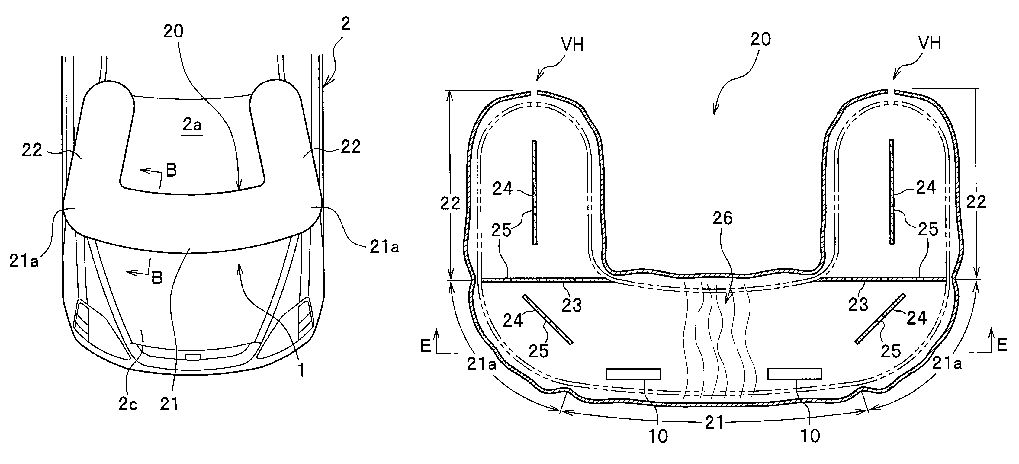
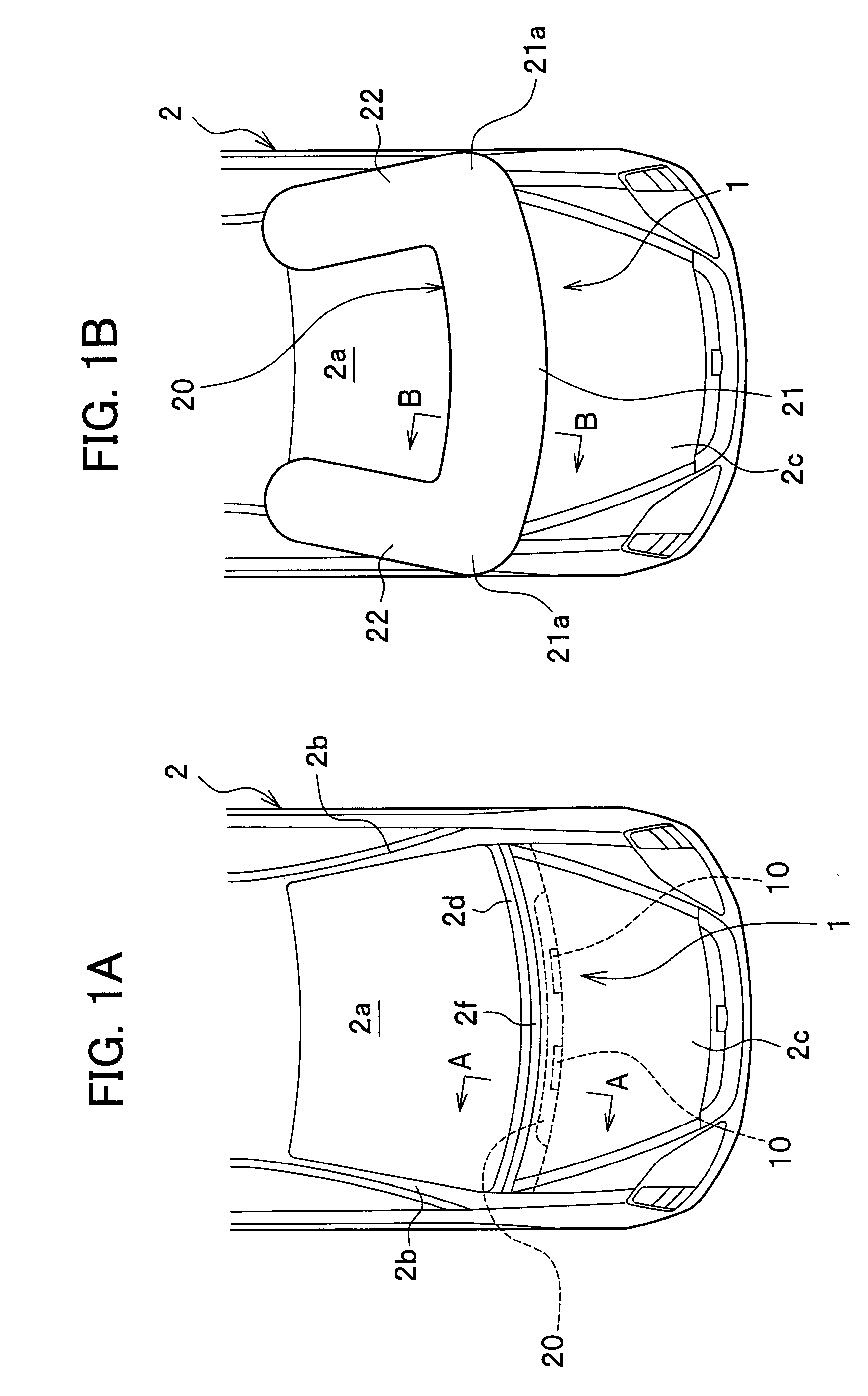
[0039]As shown in FIGS. 1A and 1B, the collision object protection device 1 mainly includes a collision detection device (not shown) which detects or predicts a collision of a vehicle 2 with a collision object (not shown) such as a pedestrian, two inflators 10, 10 which generate a gas as soon as the collision detection device detects or predicts a collision of the vehicle 2 with a collision object, and an air bag 20 which is inflated and expanded on the vehicle 2 by the gas generated by the inflators 10, 10.

[0040]The collision detection device includes an ECU (Electronic Control Unit) which detects or predicts a collision of the vehicle 2 with a collision object based on a signal from a sensor (not shown) or radar (not shown) mounted on the vehicle 2. The collision detection device operates two inflators 10, 10 so...

second embodiment

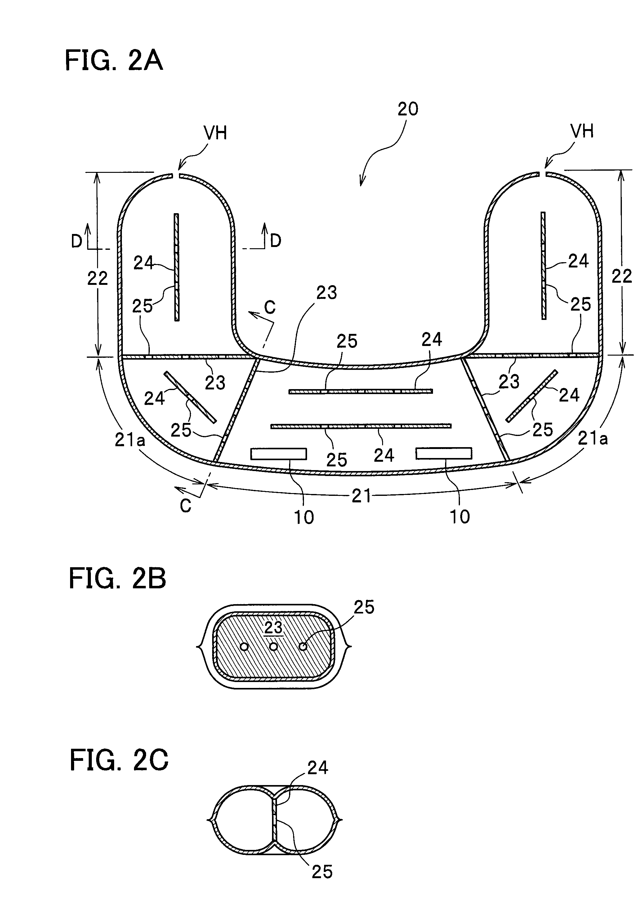
[0062]With reference to FIGS. 6A and 6B, a collision object protection device according to a second embodiment of the present invention will be described below. In FIGS. 6A and 6B, the air bag that has not been inflated and expanded is indicated by solid line, and the air bag that has been inflated and expanded is indicated (except the first and second tethers) by two-dot chain line. The collision object protection device according to the second embodiment is substantially the same as the collision object protection device according to the first embodiment except for the configuration of the air bag 20, and therefore description will be given only to the air bag 20. In the drawings, parts similar to those previously described with reference to the first embodiment are denoted by the same reference numerals, and detailed description thereof will be omitted.

[0063]As shown in FIG. 6A, a first tether 23 is arranged inside the air bag 20 respectively at boundaries between the pillar base...

third embodiment

[0071]With reference to FIG. 7, a collision object protection device according to a third embodiment of the present invention will be described below. The collision object protection device according to the third embodiment is substantially the same as the collision object protection device according to the first embodiment except for the configuration of the air bag 20, and therefore description will be given only to the air bag 20. Parts similar to those previously described with reference to the first embodiment are denoted by the same reference numerals, and detailed description thereof will be omitted.

[0072]As shown in FIG. 7, a first tether 23 is arranged inside the air bag 20 respectively at boundaries between the pillar base portions 21a, 21a and the pillar portions 22, 22. Further, a plurality of first tethers 23 are arranged inside the air bag 20 respectively across the pillar portions 22. The plurality of first tethers 23 are spaced apart from each other in an area where ...


PUM


Abstract

A collision object protection device inflates and expands an air bag on a vehicle as soon as a collision of a collision object with the vehicle is detected or predicted. The collision object protection device includes: the air bag having a main body portion that expands along a lower part of a front windshield glass of the vehicle, a pair of pillar portions that expand along front pillars of the vehicle, and a pair of pillar base portions that connect the main body portion and the pair of pillar portions; and at least one inflator for supplying a gas to the main body portion of the air bag. A partition wall having one or more openings is arranged inside the air bag respectively at a boundary between the main body portion and the pillar base portion.

Description

CROSS REFERENCE TO RELATED APPLICATIONS[0001]This application claims the foreign priority benefit under Title 35, United States Code, §119(a)-(d) of Japanese Patent Application No. 2005-333491 filed on Nov. 18, 2005 in the Japan Patent Office, the disclosure of which is herein incorporated by reference in its entirety.BACKGROUND OF THE INVENTION[0002]The present invention relates to a collision object protection device, which absorbs an impact of a collision object such as a pedestrian upon collision with a vehicle, and protects the collision object.[0003]Recently, there has been proposed a collision object protection device which inflates and expands an air bag on a vehicle if a collision of the collision object with the vehicle is detected or predicted, so that an impact force applied to the collision object is absorbed and relieved. Such a collision object protection device is disclosed, for example, by Japanese Laid-open Patent Application No. 2000-264146 (paragraph [0015] and F...

Claims


Application Information

Patent Timeline
Patent Type & Authority Patents(United States)
IPC IPC(8): B60R21/34B60R21/36
CPCB60R21/36B60R2021/23324
Inventor OKAMOTO, YUTAKAKIKUCHI, YUJI
Owner HONDA MOTOR CO LTD
Why Eureka
Try Eureka