Photovoltaic equipment mounting device capable of automatic protection in severe weather

An automatic protection and severe weather technology, which is applied in the direction of photovoltaic power generation, photovoltaic modules, and the support structure of photovoltaic modules, can solve the problems of unusability and lack of automatic protection functions, so as to prolong the service life, avoid further damage, avoid damage effect

Inactive Publication Date: 2020-06-09
WEST ANHUI UNIV
View PDF1 Cites 2 Cited by
  • Summary
  • Abstract
  • Description
  • Claims
  • Application Information

AI Technical Summary

Problems solved by technology

[0002] Photovoltaic is the abbreviation of solar photovoltaic power generation system. Now the use of new energy is becoming more and more extensive, and photovoltaic equipment has gradually developed from land to offshore photovoltaic. After retrieval, the Chinese patent authorization number is CN108322158A, which discloses a floating offshore photovoltaic support , including the air cushion, the side frame of the photovoltaic module set on the air cushion, several elastic buffers are arranged in the air cushion, the two ends of the elastic buffer are fixedly connected to the upper inner wall and the lower inner wall of the air cushion, and the upper surface of the air cushion is harder than the lower surface of the air cushion The hardness, there is a distance between adjacent elastic buffers, and the guides of the elastic buffers are fixed in the air cushion. The above patents have the following deficiencies: they cannot be used in bad weather, and they do not have automatic protection functions, which the above patents cannot solve. Such problems, therefore, urgently need a kind of bad weather can automatically protect the photovoltaic equipment installation device to solve the above problems

Method used


Image

  • Photovoltaic equipment mounting device capable of automatic protection in severe weather
  • Photovoltaic equipment mounting device capable of automatic protection in severe weather
  • Photovoltaic equipment mounting device capable of automatic protection in severe weather

Examples


Embodiment Construction

[0025] The following will clearly and completely describe the technical solutions in the embodiments of the present invention with reference to the accompanying drawings in the embodiments of the present invention. Obviously, the described embodiments are only some, not all, embodiments of the present invention.

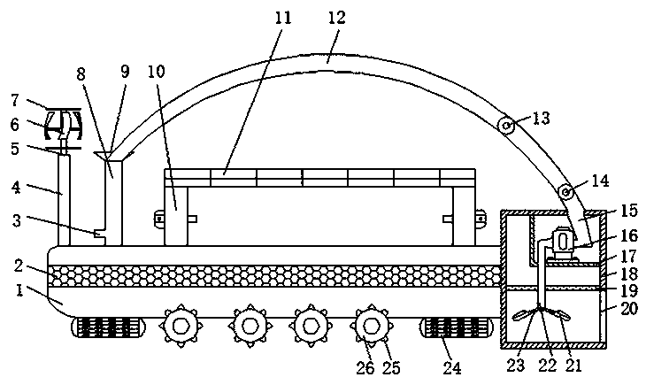
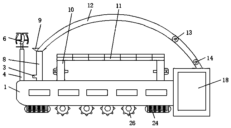
[0026] refer to Figure 1-5 , a photovoltaic equipment installation device that can be automatically protected in bad weather, including a housing 1, first through holes equidistantly distributed on the outer wall of the bottom of the housing 1, and impellers 26 are fixed on the circumferential inner walls of the first through holes by bolts , the outer circumferential wall of the impeller 26 is welded with equidistantly distributed half-round corners 25, both sides of the outer wall of the bottom of the housing 1 are fixed with tires 24 by bolts, and the inner wall of one side of the housing 1 is fixed with a screen 2 by bolts, When the sea environment is bad, there...


PUM


Abstract

The invention discloses a photovoltaic equipment mounting device capable of automatic protection in severe weather. In view of the problems of being unable to use in severe weather and having no automatic protection function, the device in the scheme comprises a shell; first through holes distributed at equal intervals are formed in the outer wall of the bottom of the shell; impellers are fixed tothe inner walls of the circumferences of the first through holes through bolts; semi-circular corners distributed at equal intervals are welded to the outer walls of the circumferences of the impellers; tires are fixed to the two sides of the outer wall of the bottom of the shell through bolts; and a screen is fixed to the inner wall of one side of the shell through bolts. Photovoltaic equipmentis prevented from being submerged by seawater; damage to photovoltaic equipment is avoided, marine residues are prevented from being wound into the shell through the semi-circular corners, mess is avoided, the residues are prevented from being beaten to the surface of the shell through seawater through the screen, the pulleys are driven by the submersible pump to be pushed forwards through kineticenergy of the seawater, and therefore the elastic cloth is pulled and covers the photovoltaic equipment as a whole.

Description

technical field [0001] The invention relates to the technical field of installation devices, in particular to a photovoltaic equipment installation device that can automatically protect against bad weather. Background technique [0002] Photovoltaic is the abbreviation of solar photovoltaic power generation system. Now the use of new energy is becoming more and more extensive, and photovoltaic equipment has gradually developed from land to offshore photovoltaic. After retrieval, the Chinese patent authorization number is CN108322158A, which discloses a floating offshore photovoltaic support , including the air cushion, the side frame of the photovoltaic module set on the air cushion, several elastic buffers are arranged in the air cushion, the two ends of the elastic buffer are fixedly connected to the upper inner wall and the lower inner wall of the air cushion, and the upper surface of the air cushion is harder than the lower surface of the air cushion The hardness, there ...

Claims


Application Information

Patent Timeline
Patent Type & Authority Applications(China)
IPC IPC(8): H02S20/00H02S20/30H02S40/00B63B35/44
CPCB63B35/44B63B2035/4453H02S20/00H02S20/30H02S40/00Y02E10/50
Inventor 王洪新孙闯张伟沙美妤琚凯高金虎
Owner WEST ANHUI UNIV
Why Eureka
Try Eureka