Water jet processing method

a technology of water jets and processing methods, applied in the field of water jet processing methods, can solve the problem of unlikely bounce of processing water, and achieve the effect of preventing abnormal processing and damag

Active Publication Date: 2009-09-08
DISCO CORP
View PDF11 Cites 27 Cited by
  • Summary
  • Abstract
  • Description
  • Claims
  • Application Information

AI Technical Summary

Benefits of technology

[0009]Accordingly, it is an object of the present invention to provide a water jet processing method that can prevent abnormal processing and damage occurring when cut lines are made by water jet to intersect with each other, thereby providing satisfactory products.
[0011]Preferably, in the second cutting step relative movement between the nozzle and the holding means is once lowered when water jet enters and cuts the anteroposterior section at the second speed. First, the relative travel speed of the water jet in front of the intersection of the second predetermined cutting line with the first cut line is made lower; therefore, the angle θ of the delay-inclination shown in FIG. 7 is reduced to a near-zero angle. Thus, the escape of the water jet does not occur, which can reduce an insufficient processing area. In addition, the occurrence of the insufficient processing area can be suppressed depending on the travel speed. As a result, the occurrence of the projections 9 shown in FIGS. 8A and 8B can be prevented.
[0012]Next, when the second cut line is formed after it has traversed the first cut line, that is, the relative travel speed is lowered when the water jet is moved rearward of (to the leading side of the moving direction) the intersection of the cut lines, the water jet does not collide with the wall of the material to be cut, but slowly hits it to gradually carve the wall, forming the second cut line. Thus, the bounce of the processing water is unlikely to occur. That is to say, it can be prevented that the bounce of the processing water damages the vicinity of the opening of the second cut line to the first cut line.
[0015]In the present invention, when the water jet to form the second cut line is immediately anterior to the intersection of the cut lines and enters the low-speed travel period, the relative movement of the jet water, i.e., the relative movement of the nozzle and the holding means, may be stopped once. If such operating mode is taken, the inclination angle θ formed at the front edge of the water jet is eliminated immediately anterior to the interval. In other words, the delay-inclination is eliminated and then the water jet is moved to the intersection with the first cut line at a low speed. Consequently, it is more ensured to produce an effect of preventing the occurrence of the insufficient processing area, compared with the case where the water jet is moved at a low speed with the delay-inclination left.
[0016]According to the water jet processing method of the present invention, abnormal processing or damage can be prevented that has otherwise been produced when the second cut line is made to intersect the first cut line, thereby producing an effect of providing satisfactory products.

Problems solved by technology

Thus, the bounce of the processing water is unlikely to occur.

Method used


Image

  • Water jet processing method
  • Water jet processing method
  • Water jet processing method

Examples


working example

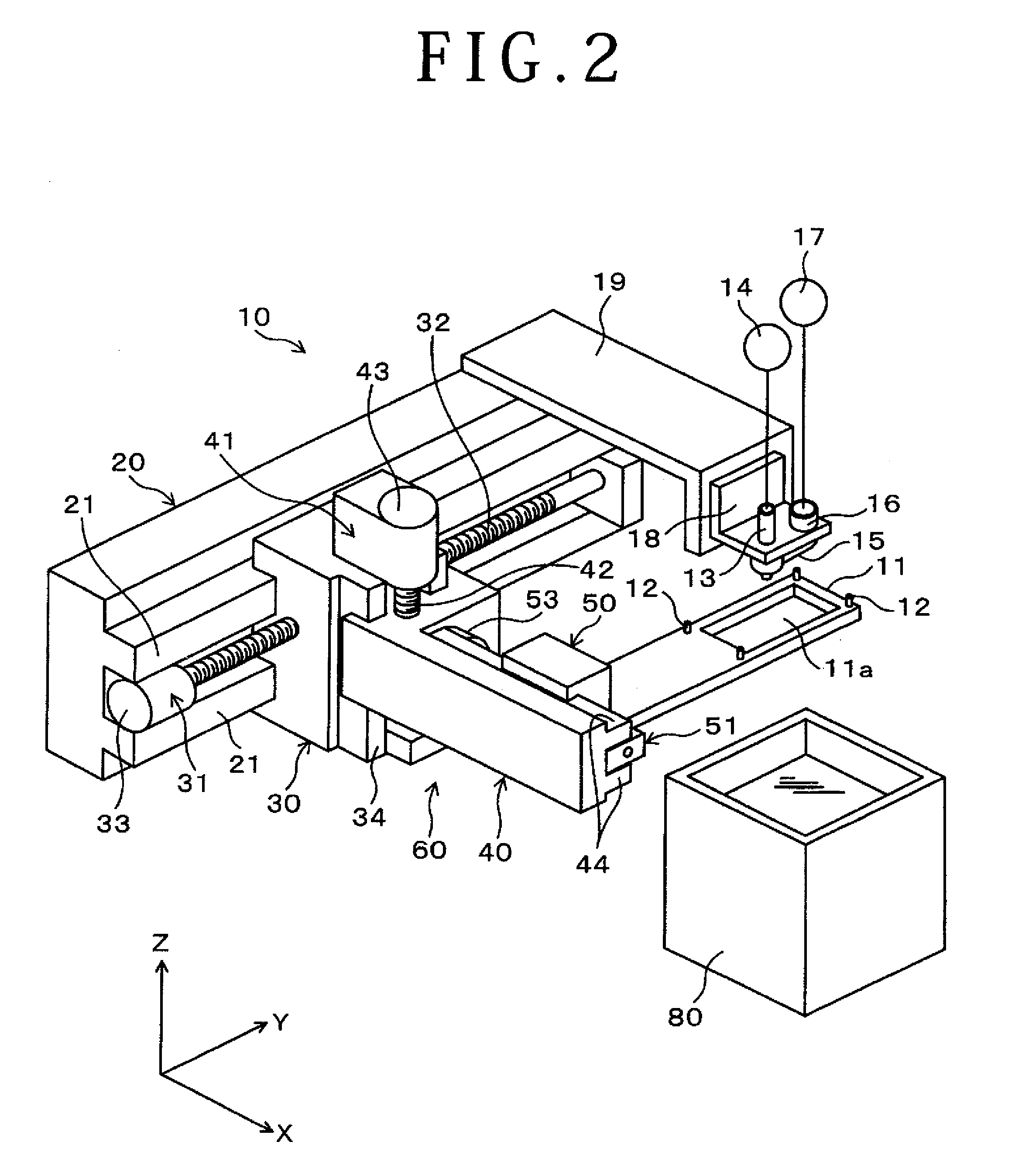
[0060]A glass epoxy plate with a thickness of 3 mm is cut in a cross shape by the same water jet processing machine as that illustrated in FIG. 2. Initially, a first predetermined cutting line to be cut first was cut by water jet emitted from a nozzle at a relative travel speed of 35 mm / sec. Incidentally, it was grasped that an angle θ of delay-inclination occurring at this time as shown in FIG. 3B was about 14.5° and the distance d is about 0.8 mm. Next, a second predetermined cutting line crisscross intersects the first cut lines thus formed was cut at 35 mm / sec at a portion thereof immediately anterior to the intersection. When a position to within 0.9 mm of the first cut line is reached, the relative travel speed of the nozzle is decelerated to 3 mm / sec and the intersection is traversed to form a second cut line.


PUM

PropertyMeasurementUnit
emission-distanceaaaaaaaaaa
thicknessaaaaaaaaaa
relative travel speedaaaaaaaaaa

Abstract

In a water jet processing method, when a nozzle adapted to emit water jet is moved relatively to a substrate to form a second cut line intersecting a first cut line, the relative travel speed of the nozzle is set to a second speed lower than a first normal speed by about 1 / 5 to 1 / 20 at least in a section anteroposterior to the intersection. Delay-inclination of a front edge of the second cut line is eliminated as much as possible to thereby prevent the occurrence of an insufficient processing area.

Description

BACKGROUND OF THE INVENTION[0001]1. Field of the Invention[0002]The present invention relates to water jet processing methods of cutting a platelike workpiece made of a relatively brittler material by producing a jet of high-pressure processing water directed to the workpiece. In particular, the invention relates to such a water jet processing method in the case where cutting lines are intersected with each other.[0003]2. Description of the Related Art[0004]Substrates mounted thereon with e.g. a semiconductor device are frequently made of a brittle material such as glass epoxy, glass composite or the like. The glass epoxy is made by impregnating an epoxy resin into a stack of glass fiber-made fabrics. The glass composite is made by impregnating an epoxy resin into a stack of cut and trimmed glass fibers. Such brittle substrates are obtained by cutting one large material in a lattice pattern. The water jet mentioned above in which high-pressure processing water is jetted to a workpie...

Claims


Application Information

Patent Timeline
Patent Type & Authority Patents(United States)
IPC IPC(8): B24C1/00
CPCB26F3/004B24C1/00Y10T83/04
Inventor KANAI, SHIGEKAZUHANAJIMA, SATOSHI
Owner DISCO CORP
Why Eureka
Try Eureka