Image transmission system from three rod lenses for rigid endoscopes

a technology of rigid endoscopes and transmission systems, applied in the field of rod lens systems as image transmission systems, can solve the problems of marked darkening of the proximal image and the distal starting image, and achieve the effects of reducing production costs, reducing imaging errors, and reducing the number of components

Active Publication Date: 2009-09-08
KARL STORZ GMBH & CO KG
View PDF8 Cites 6 Cited by
  • Summary
  • Abstract
  • Description
  • Claims
  • Application Information

AI Technical Summary

Benefits of technology

[0013]The aim of the invention, therefore, is to produce the brightest possible image with the simplest possible construction of the rod lens system and with a correction of the imaging error that is comparable to the prevailing state-of-the-art for this product. At the same time, the number of components as well as the production cost should remain low.

Problems solved by technology

These image transmission systems make possible a good correction of the astigmatism and image field curvature, but have the disadvantage that the transmitted proximal image is markedly darker than the distal starting image.

Method used


Image

  • Image transmission system from three rod lenses for rigid endoscopes
  • Image transmission system from three rod lenses for rigid endoscopes
  • Image transmission system from three rod lenses for rigid endoscopes

Examples


first embodiment

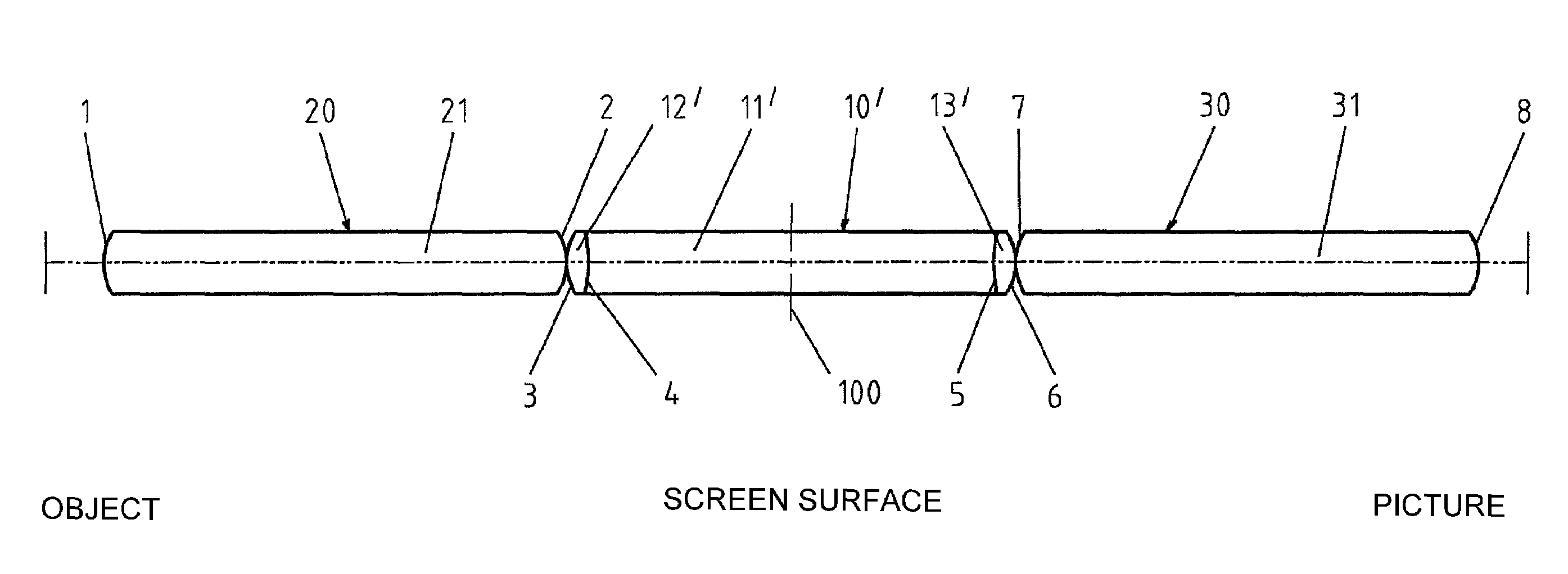
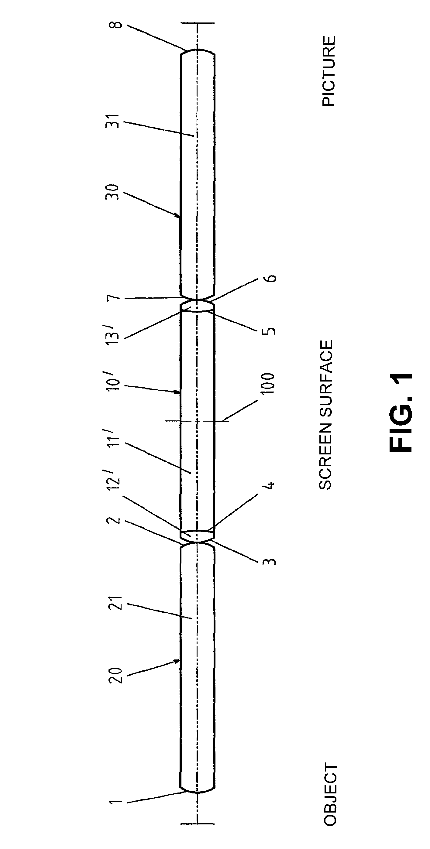
[0030]In the first embodiment as seen in FIG. 1, on a center biconcave rod lens main element (11′), which is symmetrical with respect to the center plane (100) that is perpendicular to the optical axis, biconvex lens elements (12′, 13′) are cemented to both sides, while the two outer rod lenses (20, 30) are uncemented, identical, biconvex, and arranged symmetrically with respect to the aforementioned center plane (100). In addition, the center rod lens (10′) is longer than the two outer rod lenses (20, 30). These outer rod lenses are, according to the invention, vertex-to-vertex adjacent on the center connecting rod lens (10′). A distancing tube, to distance the individual lenses (10′, 20, 30) on the radial outside of these lenses, is thus not provided. In this embodiment and those that follow, all lens elements are of an optically homogenous material and all optically active surfaces (1, 2, 3, 4, 5, 6, 7, 8) of all indicated rod lenses are spherical. This embodiment has the advanta...

embodiment 1

[0031 can, for instance, be produced according to the following table:

[0032]

Index ofSurface No.RadiusDistanceRefractionAbbe NumberIntermediatePlane6.5AirImage134.752.01.6236.42−34.70Air353.52.51.5757.54−14.846.01.6236.4514.82.51.5757.56−53.50Air734.752.01.6236.48−34.76.5AirIntermediatePlane0AirImage

second embodiment

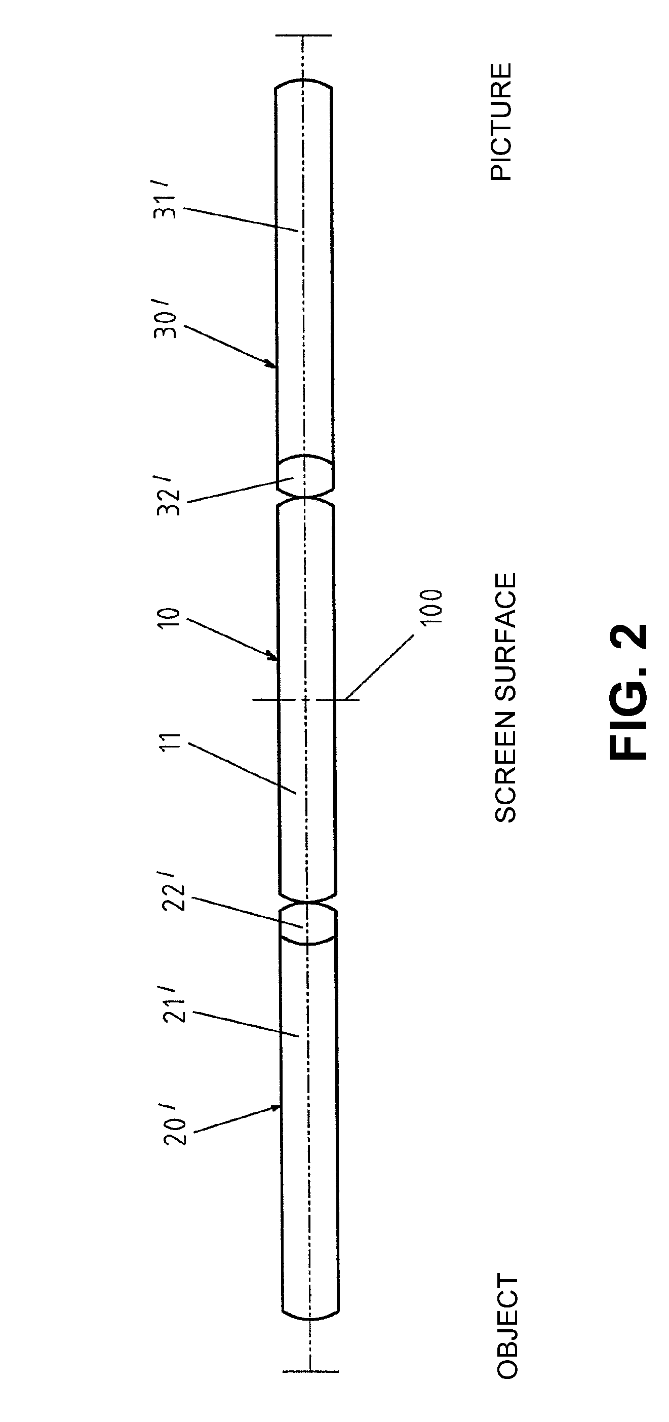
[0033]This embodiment can be modified as a second embodiment, as shown in FIG. 7, so that the center symmetrical rod lens main element is produced as biconvex element (11), and meniscus elements (12″, 13″), rather than convex lens elements, can be cemented to it. The center rod lens main element in this case can advantageously be produced similarly or even identically to the outer lenses.


PUM


Abstract

The invention relates to an image transmission system for rigid endoscopes, having a central rod lens and two outer rod lenses, which are symmetrical in respect to one another in relation to a vertical central plane of the image transmission system relative to the optical axis, wherein all lens elements consist of optically homogenous material, all optically active surface are spherical and two lens elements are stuck to on another facing each other or facing away from one another on the opposite sided of the central and outer lenses in the main lens elements of the rod lenses so that the resulting composite lens is biconvex. According to the invention, the rod lenses are arranged apex to apex next to one another and the central rod lens is substantially as long as or longer than the outer rod lenses. The solution according to the invention provides an image that is as light as possible at a given transmission length, wherein the structure of the rod lens system is simple and imaging errors can be corrected as in prior art. The number of components and production complexity are low.

Description

CROSS-REFERENCE TO RELATED APPLICATIONS[0001]This application is a continuation of pending International Patent Application No. PCT / EP02 / 08035 filed Jul. 19, 2002 which designates the United States and claims priority of pending German Application No. 10136117.3 filed Jul. 26, 2001.FIELD OF THE INVENTION[0002]The invention relates to a rod lens system as an image transmission system for rigid endoscopes and similar viewing tubes for transmitting a distal intermediate image into a proximal intermediate image.BACKGROUND OF INVENTION[0003]Endoscopes and the aforementioned viewing tubes, in addition to applications in medicine, are also used in technology for observations in hollow spaces such as bodily cavities, combustion chambers of engines, power systems, and the like. Depending on the depth of the cavity to be investigated, various transmission lengths need to be bridged by means of the rod lens system.[0004]Therefore, image transmission systems called relay lens systems are also u...

Claims


Application Information

Patent Timeline
Patent Type & Authority Patents(United States)
IPC IPC(8): G02B23/24
CPCG02B23/2446
Inventor LEI, FANG
Owner KARL STORZ GMBH & CO KG
Why Eureka
Try Eureka