Integrated functionality in optical backplane

Inactive Publication Date: 2009-09-08
LOCKHEED MARTIN CORP
View PDF23 Cites 7 Cited by
  • Summary
  • Abstract
  • Description
  • Claims
  • Application Information

AI Technical Summary

Benefits of technology

[0008]The present invention, at least in one or more embodiments, provides the ability to effectively integrate passive and active functionality into an optical backplane system. For example, functional optical devices may be provided with a fixed configuration of input and

Problems solved by technology

Such assembly is generally difficult and costly.
The count of splitters does not need to be very large before such connectorization and attachment becomes bulky and cumbersome to package.
Further, manufacturing costs of adding su

Method used


Image

  • Integrated functionality in optical backplane
  • Integrated functionality in optical backplane
  • Integrated functionality in optical backplane

Examples


Embodiment Construction

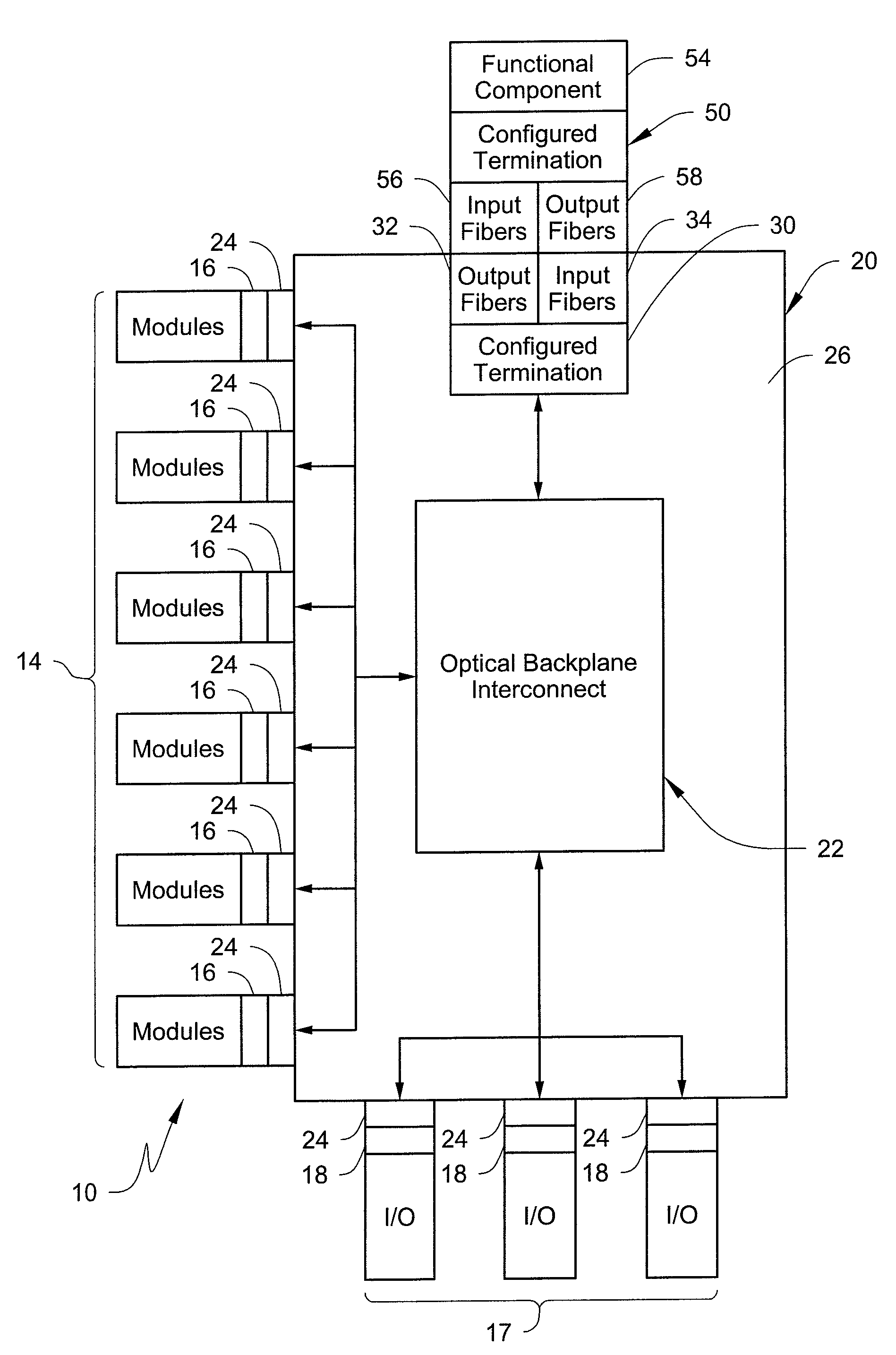
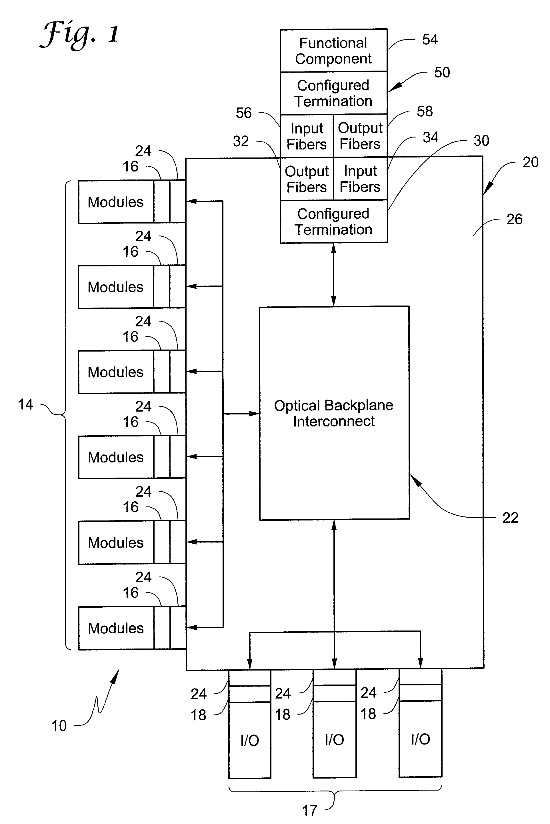
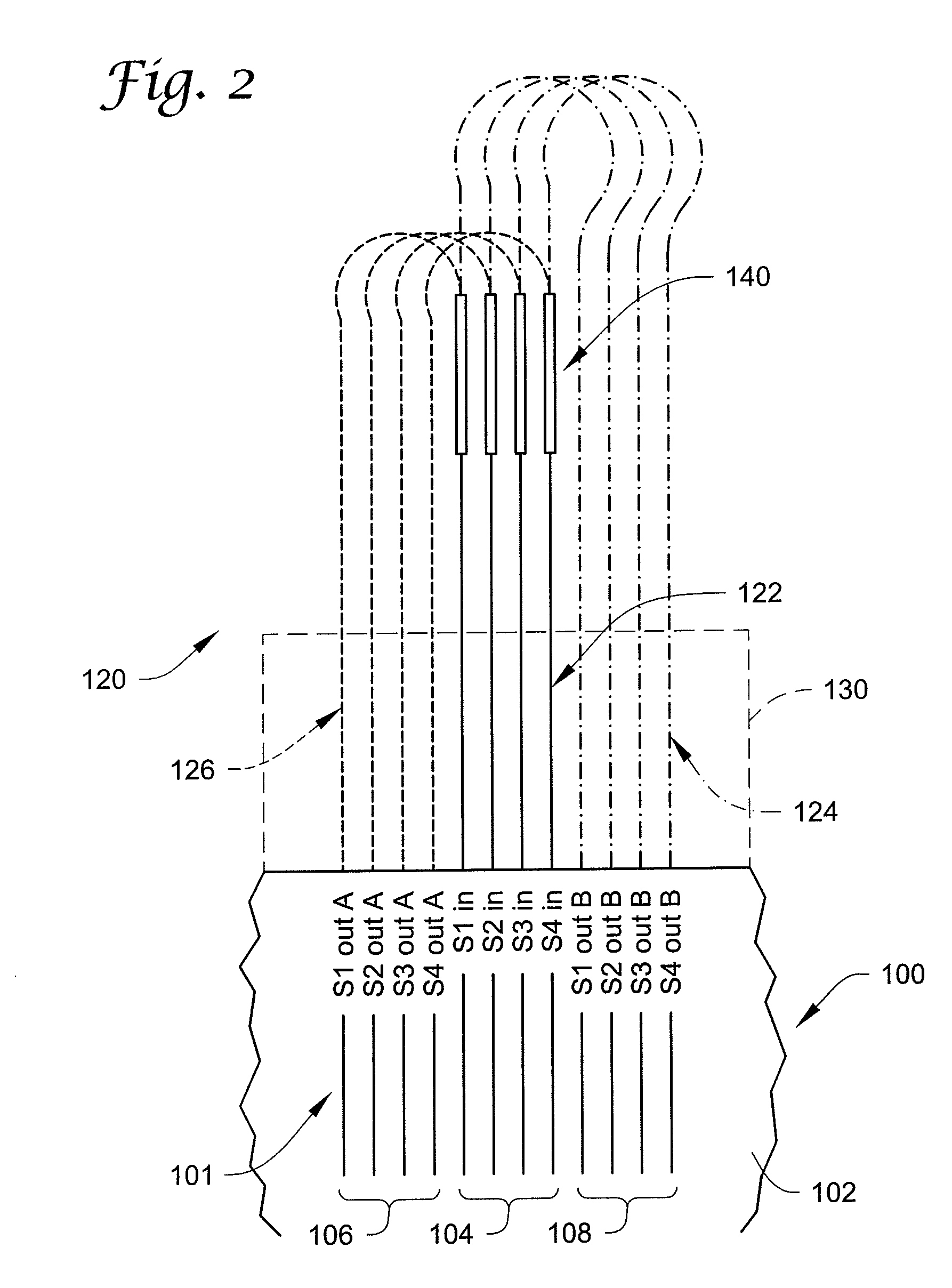
[0021]Generally, an optical backplane system 10, according to the present invention, shall be described with reference to FIG. 1, along with a functional optical device 50 integrated therewith. One or more embodiments of the functional optical device 50 shall further be described in more detail with reference to FIGS. 2 and 3.

[0022]Generally, and as further described herein, optical backplane system 10 includes an optical backplane interconnect 20 for providing an optical pathway 22 between a plurality of optical nodes. The optical pathway 22 includes a plurality of optical fibers for use in optical signal transmission. Such optical fibers of the optical pathway 22 are terminated at a plurality of connector components 24 (e.g., ferrules used to terminate a plurality of fibers).

[0023]As used herein, an optical node may be any connection point associated with or otherwise connectable using the optical backplane system 10. For example, optical nodes may include one or more modules 14 a...


PUM


Abstract

A functional optical device for use in an optical backplane system is provided that includes one or more input fibers, one or more output fibers, and a functional portion configured to operate on an optical input received via the one or more input fibers to provide an optical output via the one or more output fibers. The one or more input fibers and the one or more output fibers of the functional optical device are terminated in a fixed configuration based on a fixed termination layout of at least one group of multiple fibers of an optical backplane interconnect.

Description

BACKGROUND OF THE INVENTION[0001]The present invention relates generally to fiber optics. More particularly, the present invention relates to optical backplane systems, as well as methods and devices associated with such optical backplane systems.[0002]Optical fiber has been widely accepted as an interconnection medium for communication networks, due mainly to the advantages offered by fiber, such as higher bandwidths and better noise performance, as compared to electrical media. For example, an optical network can be used to optically connect any number of optical nodes of a system. For example, an optical network can be used to connect a plurality of processors for interprocessor communication.[0003]An optical backplane system is a structure including a variety of connectors facilitating the interconnection and communication of different systems and components. Generally, the optical backplane system is configured for the interconnection of systems and components having high bandw...

Claims


Application Information

Patent Timeline
IPC IPC(8): G02B6/00
CPCG02B6/43G02B6/2804
Inventor THORSON, KEVIN J.STEVENS, RICK C.NELSON, RYAN L.
Owner LOCKHEED MARTIN CORP
Why Eureka
Try Eureka