Web processing device and web processing method

a processing device and a technology of web processing, applied in the field of web processing device and web processing method, can solve the problems of shortening the lifetime of the pad, and hindering the change of the attitude of the pad when the pad rotates, so as to facilitate the handover of the web and hinder the pad from changing its attitud

Active Publication Date: 2009-09-15
ZUIKO CORP
View PDF19 Cites 242 Cited by
  • Summary
  • Abstract
  • Description
  • Claims
  • Application Information

AI Technical Summary

Benefits of technology

[0009]In a conventional device, where a continuous web is cut and carried while the attitude thereof is changed by means of a single rotating unit, the cutter is received by a pad or an anvil integrated with a pad when cutting the web. With such a configuration, however, the web-cutting load acts upon the pad, thus shortening the lifetime of the pad. If an anvil for receiving the cutter is provided separately from the pad so as to prevent the web-cutting load from acting upon the pad, the anvil may hinder the change of the attitude of the pad when the pad rotates.
[0015]Thus, while the pads rotate around a single rotating unit, to carry the web, it is possible both to cut the web and to change the attitude thereof. Therefore, it is possible to reduce the cost and the size of the processing device.
[0016]In a case where the continuous web includes an elastic member and the continuous web therefore has a contractile force along the direction in which the continuous web is carried, since the web is received onto the pad while being in the form of an uncut continuous web, it is possible to prevent the web from shrinking after being cut. Thus, since it is possible to prevent the shrinking of the web, it is easy to process the web after it is cut.
[0020]If the holding surface of the pad is flat as described above, both end portions of the pad opposing each other in the direction along the axis of the rotating unit come close to the surface of the downstream transfer device after the pad turns by 90 degrees. Therefore, the handover of the web is facilitated.
[0021]A processing method of the present invention is a web processing method for receiving a tip portion of a continuous web at a receiving position, for carrying a cut-off web cut out from the tip portion to a hand-over position downstream of the receiving position while changing an attitude of the cut-off web, and for handing over the cut-off web to a downstream transfer device at the hand-over position, the method using a rotating unit and a cutter. The rotating unit used in the present method includes a plurality of pads and a plurality of anvils, which are arranged alternately around the rotating unit and which revolve generally in a circumferential direction of the rotating unit. The cutter used in the present method is capable of cutting off a tip portion of the continuous web, together with the anvil, at a cutting position downstream of the receiving position. The method comprises: a step in which the pad receives the continuous web; a step in which the cutter cuts the continuous web at the cutting position, together with the anvil positioned at a first relative level with respect to a surface of the pad adjacent to the anvil such that the anvil can be brought into contact with the cutter; a step in which the pad revolves around an axis of the rotating unit while changing an attitude of the pad by turning about a line extending generally in a radial direction of the rotating unit, thereby carrying the cut-off web while changing an attitude of the cut-off web; and a step in which, when the pad changes its attitude, the anvil adjacent to the turning pad is relatively moved to a second relative level with respect to the surface of the pad so as not to hinder the pad changing its attitude.

Problems solved by technology

With such a configuration, however, the web-cutting load acts upon the pad, thus shortening the lifetime of the pad.
If an anvil for receiving the cutter is provided separately from the pad so as to prevent the web-cutting load from acting upon the pad, the anvil may hinder the change of the attitude of the pad when the pad rotates.

Method used


Image

  • Web processing device and web processing method
  • Web processing device and web processing method
  • Web processing device and web processing method

Examples


Embodiment Construction

[0043]The present invention will be understood more clearly from the following description of preferred embodiments taken in conjunction with the accompanying drawings. Note however that the embodiments and the drawings are given for the purpose of mere illustration and explanation and should not be used to define the scope of the present invention. The scope of the present invention can only be defined by the appended claims. In the accompanying drawings, the same reference numerals denote the same or corresponding elements throughout several views.

[0044]An embodiment of the present invention will now be described with reference to the drawings.

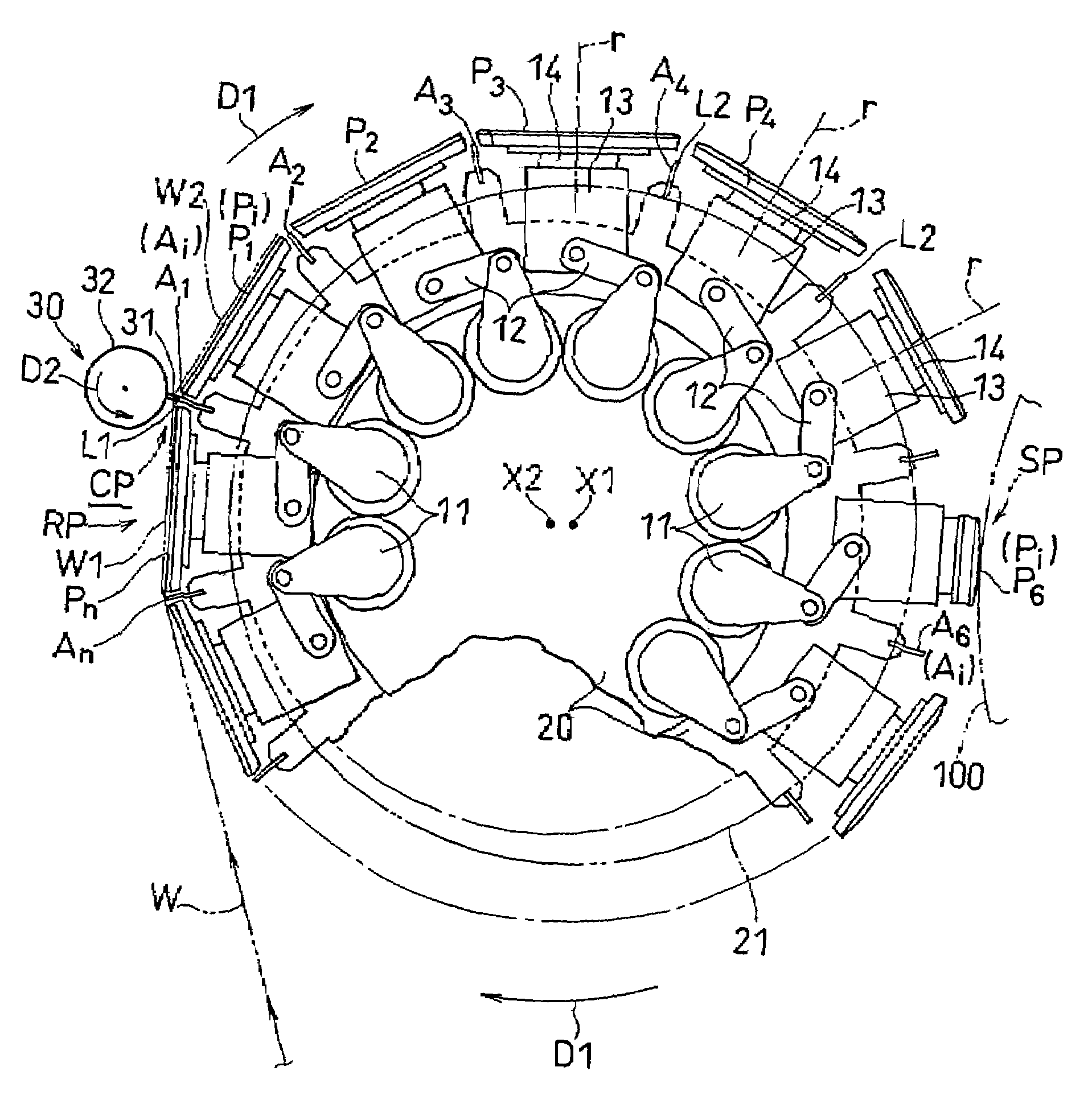
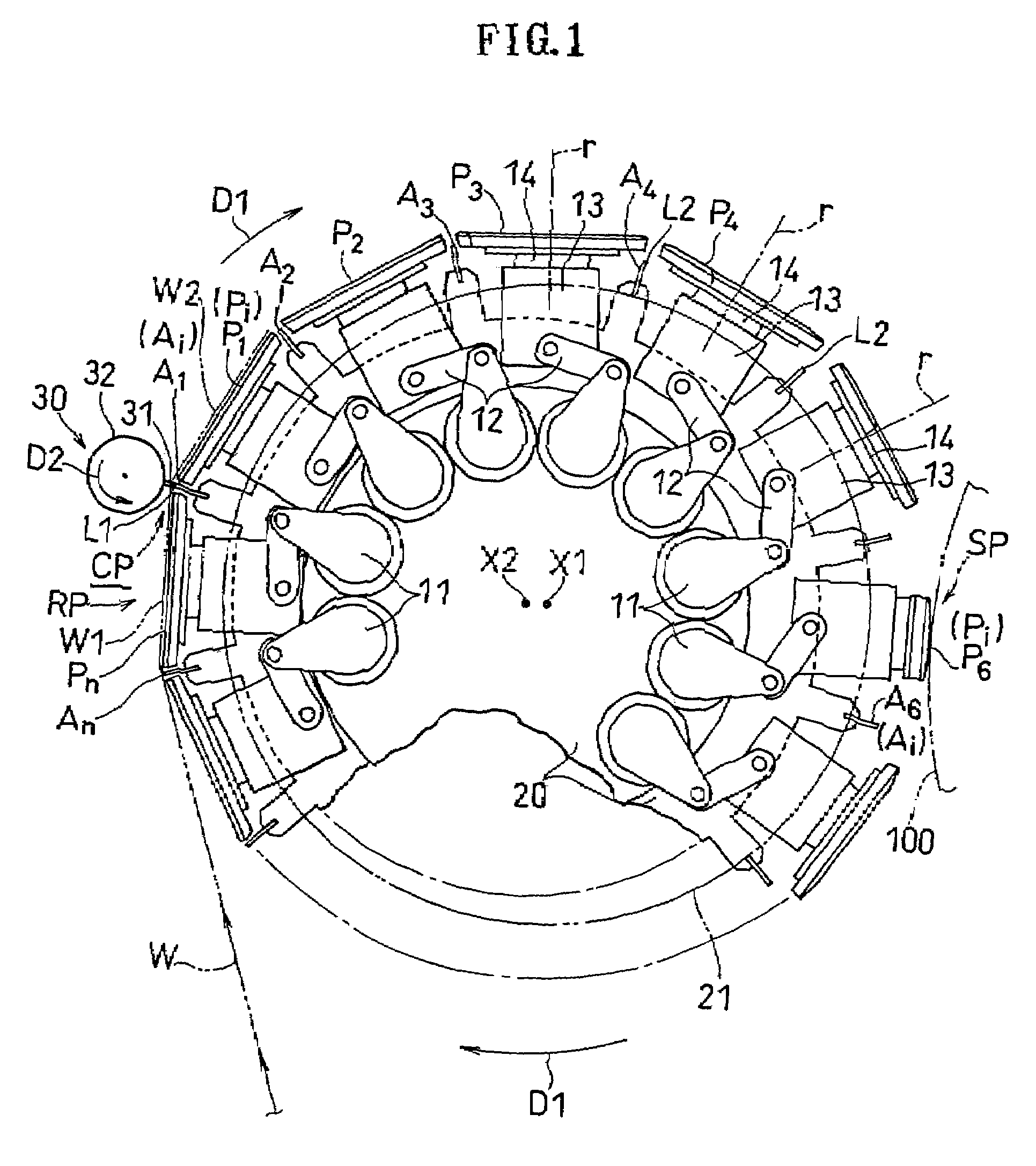
[0045]FIG. 1 is a schematic side view showing a processing device according to an embodiment of the present invention.

[0046]As shown in FIG. 1, the present device receives a tip portion W1 of a continuous web W at the receiving position RP, and cuts the continuous web W at the cutting position CP downstream of the receiving position RP. More...


PUM

PropertyMeasurementUnit
angleaaaaaaaaaa
angleaaaaaaaaaa
shapeaaaaaaaaaa

Abstract

The present invention relates to a web processing device, comprising a plurality of pads Pi revolving around a axis X1, a cutter 30 for cutting a continuous web W, and a plurality of anvils Ai for receiving the cutter 30. The pads Pi receive the continuous web W, and the cutter 30 cuts the continuous web W into a cut-off web W2 together with the anvil Ai positioned at a first relative level L1. The pad Pi revolves around the axis X1 while changing an attitude of the pad Pi by turning about a line extending from the first axis toward the pad Pi, thereby carrying the cut-off web W2 while changing an attitude of the cut-off web W2. When the pad Pi changes its attitude, the anvil Ai relatively moves to a second relative level L2 so as not to hinder the pad Pi changing its attitude.

Description

TECHNICAL FIELD[0001]The present invention relates to a web processing device and a web processing method, in which a continuous web is cut into pieces and the cut-off webs are carried while the attitude thereof is changed.BACKGROUND ART[0002]The first patent document, identified below, discloses a processing system, in which an elastic material is carried by pads, and the elastic material is cut between the pads while being stretched, after which the pads are rotated to change the attitude of the material.[0003]The device of the first patent document does not have an anvil. The elastic material can be cut without using an anvil.[0004][First Patent Document] Japanese National Phase PCT Laid-Open Publication No. 10-513086 (WO96 / 23475) (FIG. 47)[0005]The second and third patent documents, identified below, each disclose a device for cutting a continuous web while carrying the continuous web by pads to produce cut-off webs, and for widening the interval between the cut-off webs.[0006]H...

Claims


Application Information

Patent Timeline
Patent Type & Authority Patents(United States)
IPC IPC(8): B26D1/40B65H35/04B65H9/00B65H35/08
CPCB26D1/405B26D5/20B26D7/015B65H35/08B26D7/018B65H2406/3454B65H2301/33216B65H2404/411B65H2404/4121Y10T83/8739Y10T83/0515Y10T83/483Y10T83/4607
Inventor NAKAKADO, MASAKISATOH, HITOSHI
Owner ZUIKO CORP
Why Eureka
Try Eureka