Chamber clean method using remote and in situ plasma cleaning systems

a plasma cleaning and chamber cleaning technology, applied in the field of chamber cleaning methods using remote and in situ plasma cleaning systems, can solve the problem of requiring a higher volume of etchant gas than is required

Inactive Publication Date: 2009-09-15
APPLIED MATERIALS INC
View PDF36 Cites 7 Cited by
  • Summary
  • Abstract
  • Description
  • Claims
  • Application Information

AI Technical Summary

Benefits of technology

[0006]According to one embodiment the process includes performing a substrate processing operation on the substrate within a substrate processing chamber and then transferring the substrate out of the substrate processing chamber; flowing a first etchant gas into a remote plasma source, forming reactive species from the etchant gas and transporting the

Problems solved by technology

One problem with some remote plasma cleaning processes, however, is that they requir

Method used


Image

  • Chamber clean method using remote and in situ plasma cleaning systems
  • Chamber clean method using remote and in situ plasma cleaning systems
  • Chamber clean method using remote and in situ plasma cleaning systems

Examples


Embodiment Construction

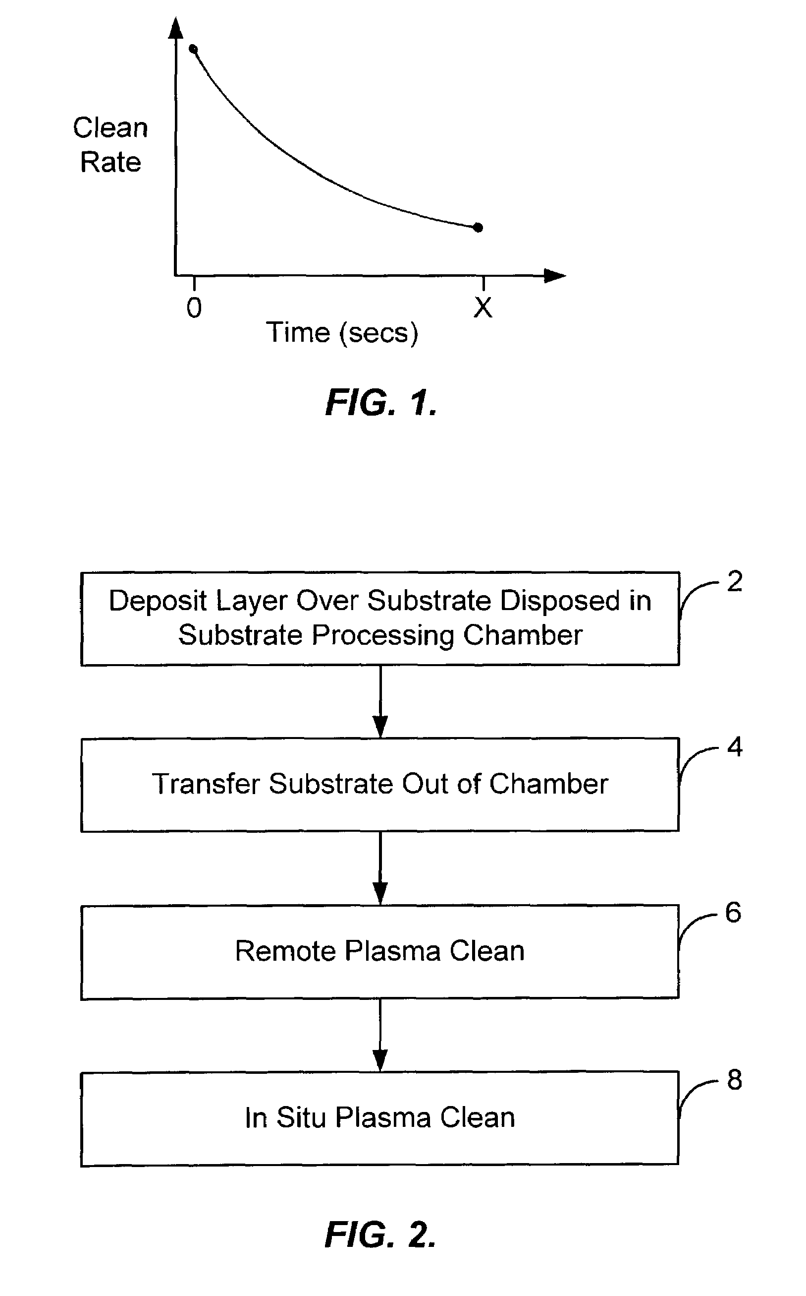
[0015]Embodiments of the present invention provide for an improved remote plasma cleaning process by reducing the amount of etchant gas required to clean unwanted deposition build-up off interior surfaces of a substrate processing chamber as compared to other remote plasma cleaning processes. Generally, remote plasma clean processes allow a higher gas dissociation rate at high gas flow rates as compared to in situ plasma clean processes. This higher ionization efficiency allows large volumes of clean gas to be flowed into the remote plasma chamber and thus leads to higher clean rates and reduced clean times as compared to in situ plasma clean processes.

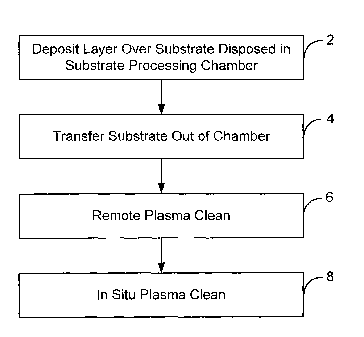
[0016]As shown in FIG. 1, however, the clean rate of a remote plasma clean process generally decreases over time as the process proceeds. At least part of the decrease in clean rate may be due to a decrease in the temperature of the chamber during the process. Typically, a remote clean process for a particular application is initiated...


PUM

PropertyMeasurementUnit
Temperatureaaaaaaaaaa
Timeaaaaaaaaaa
Flow rateaaaaaaaaaa

Abstract

A process for removing unwanted deposition build-up from one or more interior surfaces of a substrate processing chamber. According to one embodiment the process comprises performing a substrate processing operation on the substrate within the substrate processing chamber and then transferring the substrate out of the substrate processing chamber; flowing a first etchant gas into a remote plasma source, forming reactive species from the etchant gas and transporting the reactive species into the substrate processing chamber to remove a first portion of the unwanted deposition build-up; and thereafter, flowing a second etchant gas into the substrate processing chamber and forming a plasma within the substrate processing chamber from the second gas in order to remove a second portion of the unwanted deposition build-up.

Description

BACKGROUND OF THE INVENTION[0001]One of the primary steps in the fabrication of modern semiconductor devices is the formation of a layer, such as a silicon oxide layer, on a substrate or wafer. As is well known, such a layer can be deposited by chemical vapor deposition (CVD). In a conventional thermal CVD process, reactive gases are supplied to the substrate surface where heat-induced chemical reactions take place to form the desired film. In a conventional plasma CVD process, a controlled plasma is formed using, for example, radio frequency (RF) energy or microwave energy to decompose and / or energize reactive species in reactant gases to produce the desired film.[0002]Unwanted deposition on areas such as the walls of the processing chamber also occurs during such CVD processes. As is known in the industry, it is common to remove the unwanted deposition material that builds up on the interior of chamber walls with an in situ chamber clean operation. Common chamber cleaning techniqu...

Claims


Application Information

Patent Timeline
IPC IPC(8): B08B7/00B08B7/04C23C16/44
CPCC23C16/4405H01J37/32862H01J2237/022Y10S438/905
Inventor CUI, ZHENJIANGCOX, MICHAEL S.LAI, CANFENGKRISHNARAJ, PADDY
Owner APPLIED MATERIALS INC
Why Eureka
Try Eureka