Method for installing well completion equipment while monitoring electrical integrity

a technology of completion equipment and well, which is applied in the direction of fluid removal, borehole/well accessories, surveys, etc., can solve the problems of increasing the running time of the esp, the expense and time incurred in pulling the esp, tubing and power cable from the well, and the damage of the esp and power cabl

a technology of completion equipment and well, which is applied in the direction of fluid removal, borehole/well accessories, surveys, etc., can solve the problems of increasing the running time of the esp, the expense and time incurred in pulling the esp, tubing and power cable from the well, and the damage of the esp and power cabl

US7588080B2Active Publication Date: 2009-09-15BAKER HUGHES HLDG LLC

Image

  • Method for installing well completion equipment while monitoring electrical integrity
  • Method for installing well completion equipment while monitoring electrical integrity
  • Method for installing well completion equipment while monitoring electrical integrity

Examples


Embodiment Construction

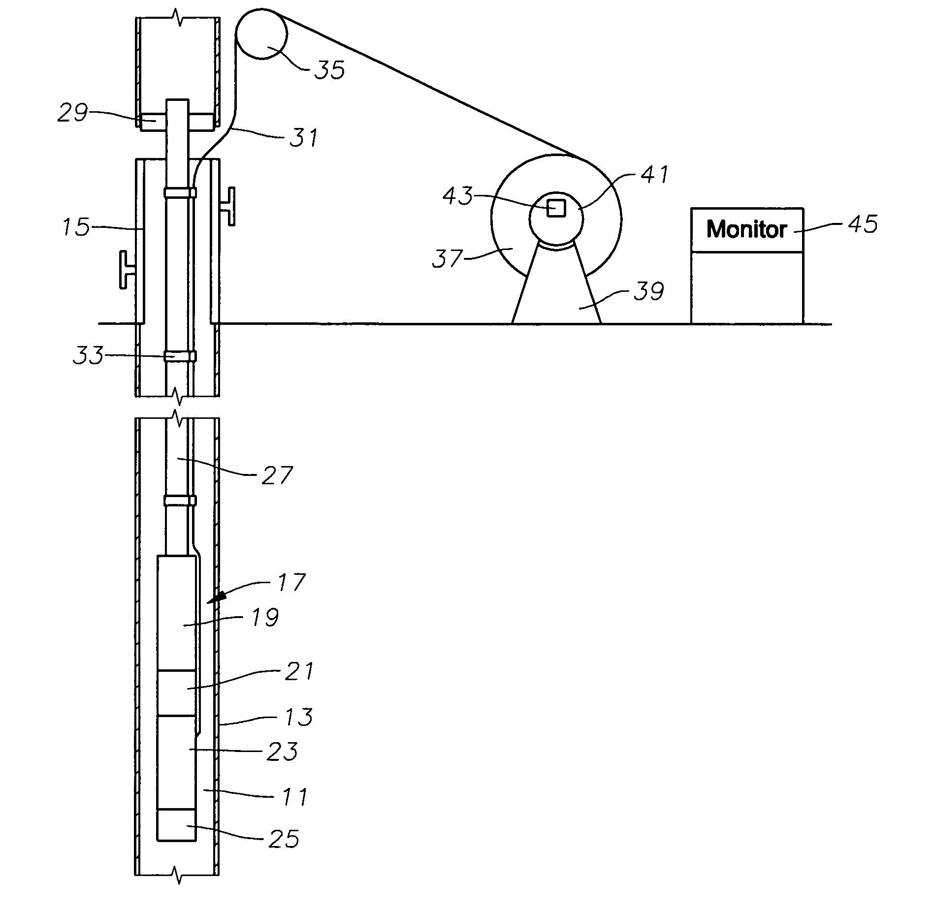
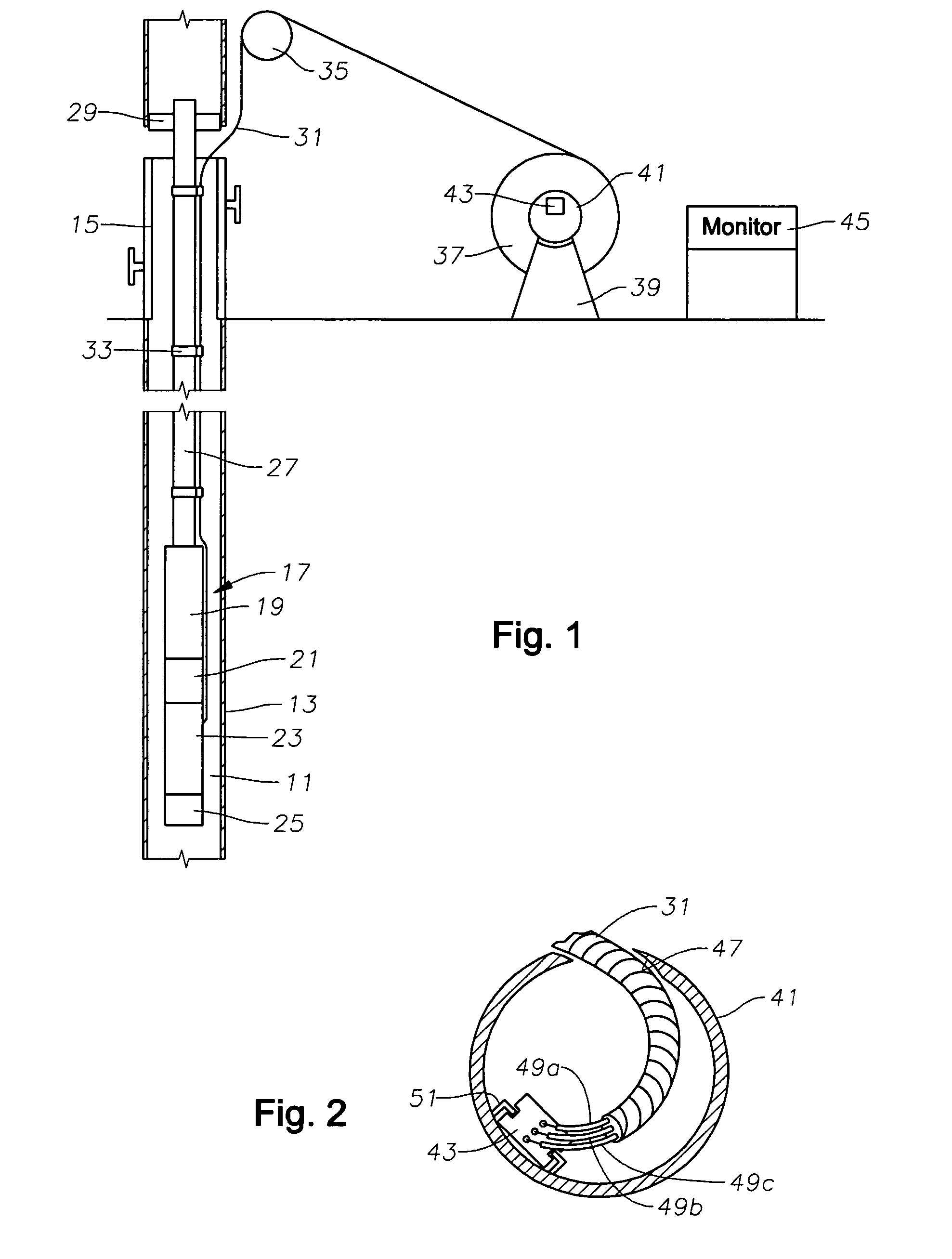
[0018]Referring to FIG. 1, a well 11 has one or more strings of casing 13 installed within the well. A production tree 15 is located at the upper end of well 11 for controlling the flow of the well fluids from well 11.

[0019]An electrical submersible pump assembly 17 (“ESP”) is shown being lowered into well 11. ESP 17 includes a centrifugal pump 19 having a large number of stages of impellers and diffusers. A seal section 21 connects the lower end of pump 19 to a motor 23. In some instances, a sensor unit 25 is secured to the lower end of motor 23 for providing signals corresponding to pressure and temperature. ESP 17 could alternately employ a progressing cavity type pump, which utilizes a stationary stator having a helical cavity. A rotor with helical lobes rotates within the stator, the rotor being driven by an electrical motor.

[0020]In this example, a string of production tubing 27 is employed to lower ESP 17 into the well. Production tubing 17 is normally made up of individual s...


PUM


Abstract

A method of installing a submersible electrical pump assembly in a well monitors the integrity of the pump assembly and electrical cable while the pump assembly is being run. The pump assembly has at least one sensor that measures a parameter in the environment of the pump assembly. A battery-powered test unit is mounted to the reel of cable, and a lead of the unit is connected to the power cable. While lowering the completion equipment, test voltage is supplied from the unit via the power cable through the motor to the sensor. The unit transmits an indication to a remote monitor that the sensor is operational.

Description

CROSS REFERENCE TO RELATED APPLICATION[0001]This application claims priority to provisional application Ser. No. 60 / 664,485, filed Mar. 23, 2005.FIELD OF THE INVENTION[0002]This invention relates in general to running into a well downhole completion equipment having electrical components, and in particular to a method for installing a submersible pump assembly while monitoring the integrity of the electrical components of the assembly.BACKGROUND OF THE INVENTION[0003]Electrical submersible pumps (ESP) are commonly used in oil wells for pumping oil and formation water to the surface. An ESP comprises a pump having a downhole electrical motor. The pump typically is a centrifugal pump having a large number of stages, each stage having an impeller and a diffuser. Alternately, the pump could be another type, such as a progressing cavity pump. The ESP may also have one or more sensors for sensing well parameters such as pressure and temperature.[0004]Normally the ESP is lowered into the w...

Claims


Application Information

Patent Timeline
15 Sep 2009
Publication
US7588080B2
IPC
E21B47/00
CPC
E21B47/00; E21B43/128
Inventors
MCCOY, ROBERT H.