Rotary fluid device performing compression and expansion of fluid within a common cylinder

a fluid device and fluid technology, applied in the direction of rotary/oscillating piston pump components, machines/engines, liquid fuel engines, etc., can solve the problems of large number of parts and large device overall size, and achieve the effect of preventing the decrease in compression efficiency and expansion efficiency, excellent sealing characteristics, and being more resistant to damag

Inactive Publication Date: 2009-09-15
DAIKIN IND LTD
View PDF17 Cites 5 Cited by
  • Summary
  • Abstract
  • Description
  • Claims
  • Application Information

AI Technical Summary

Benefits of technology

[0027]Since the swing bush (27) is provided to be in surface contact with the piston (22) and the blade (23), the contact portions achieves excellent sealing characteristics. Therefore, leakage of a refrigerant from the compression chamber (51) and the expansion chamber (52) is surely prevented, and decreases in the compression efficiency and expansion efficiency are also prevented.
[0028]Since the blade (23) is integrally provided to the cylinder (21) and supported at both ends by the cylinder (21), it is less likely to apply an abnormal concentrated load to the blade (23) and cause stress concentration during operation. Thus, the slidable portion is more resistant to damage. This feature also improves the reliability of the mechanism.

Problems solved by technology

Therefore, the overall size of the device is large, and the number of parts is also large.

Method used


Image

  • Rotary fluid device performing compression and expansion of fluid within a common cylinder
  • Rotary fluid device performing compression and expansion of fluid within a common cylinder
  • Rotary fluid device performing compression and expansion of fluid within a common cylinder

Examples


embodiment 1

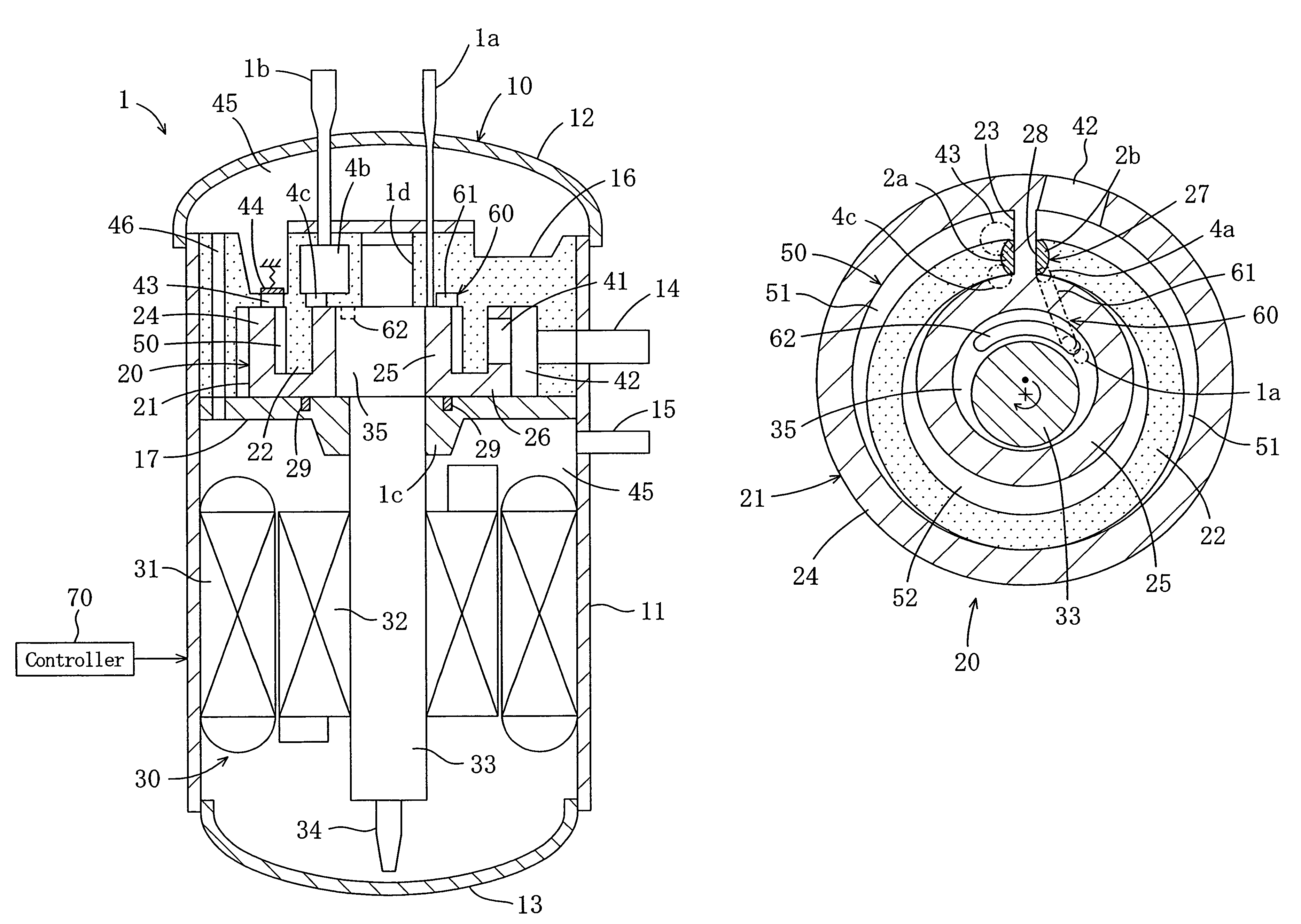
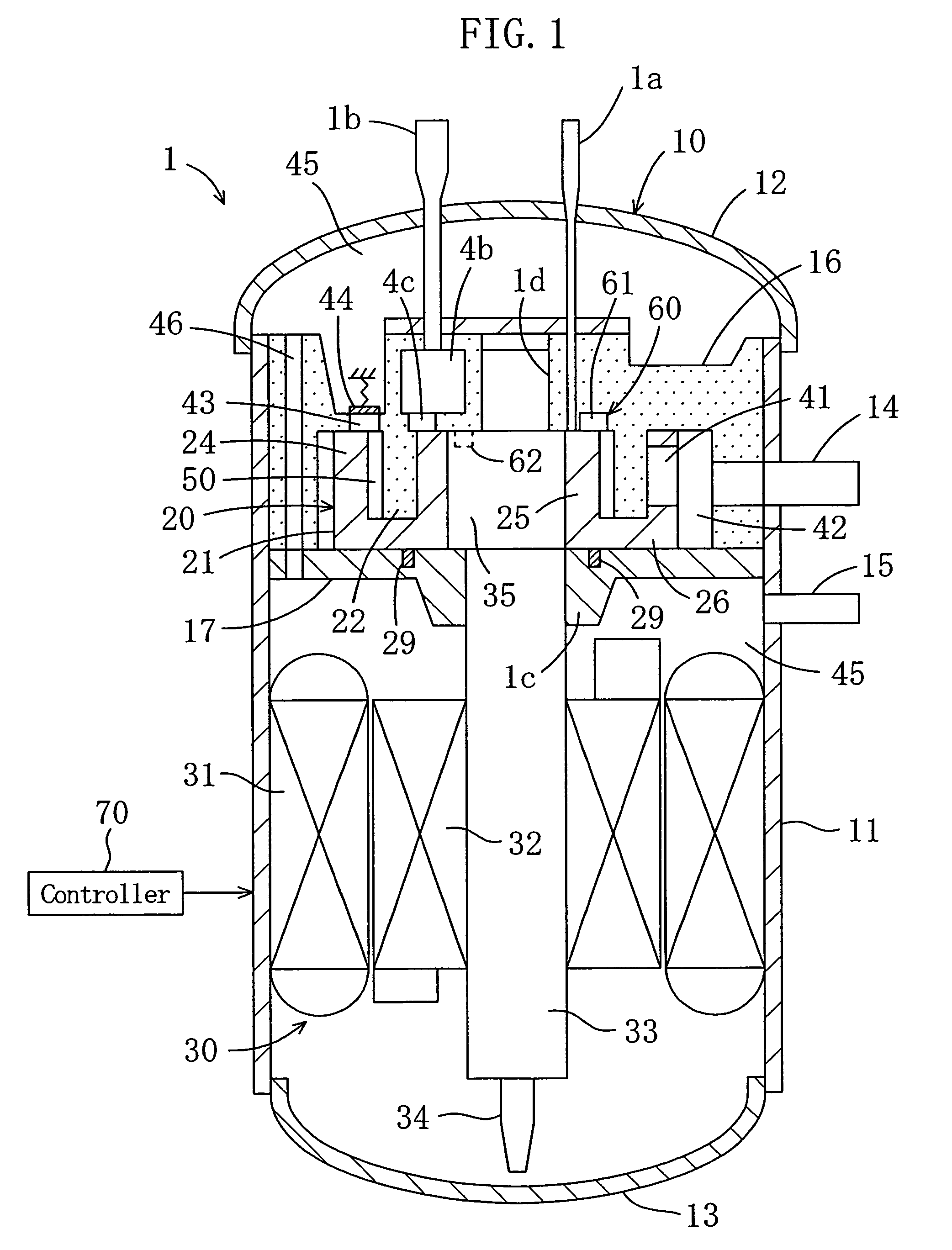
[0034]Referring to FIG. 1 to FIG. 3, this embodiment is an application of the present invention to an expansion / compression unit (1) which is a compressor including an expander. The expansion / compression unit (1) is included in a refrigerant circuit (100).

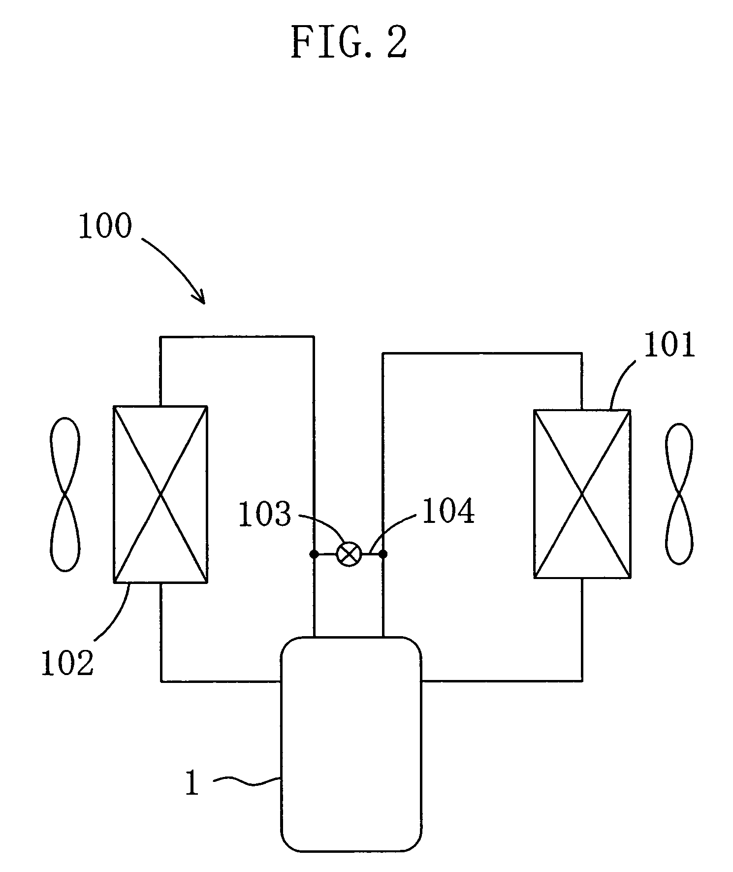
[0035]The refrigerant circuit (100) uses, for example, carbon dioxide (C02) as a refrigerant and is configured to perform at least any of a cooling operation and a heating operation by compressing CO2 over the critical pressure. The refrigerant circuit (100) includes, as shown in FIG. 2, an exterior heat exchanger (101) serving as a heat source-side heat exchanger and an interior heat exchanger (102) serving as a use-side heat exchanger, which are connected to the expansion / compression unit (1). For example, the refrigerant compressed by the expansion / compression unit (1) discharges heat in the exterior heat exchanger (101) and is then expanded by the expansion / compression unit (1). The expanded refrigerant absorbs heat in the inte...


PUM


Abstract

A rotary fluid device includes a cylinder having an annular cylinder chamber and an annular piston, which is disposed in the cylinder chamber to be eccentric relative to the cylinder. The annular piston divides the cylinder chamber into an outer working chamber and an inner working chamber. A blade is disposed in the cylinder chamber to partition each of the working chambers into a high-pressure space and a low-pressure space. The cylinder and the piston relatively rotate. The outer working chamber constitutes a compression chamber which compresses and discharges a sucked fluid with the progress of the relative rotation of the cylinder and the piston. The inner working chamber constitutes an expansion chamber which expands and discharges a sucked fluid with the progress of the relative rotation of the cylinder and the piston.

Description

CROSS-REFERENCE TO RELATED APPLICATIONS[0001]This U.S. National stage application claims priority under 35 U.S.C. §119(a) to Japanese Patent Application No. 2004-140692, filed in Japan on May 11, 2004, the entire contents of which are hereby incorporated herein by reference.TECHNICAL FIELD[0002]The present invention relates to a rotary fluid device and specifically to a rotary fluid device having a compression chamber and an expansion chamber.BACKGROUND ART[0003]Conventionally, there has been a fluid device including a compression mechanism and an expansion mechanism as disclosed in Japanese Laid Open Patent Publication No. 2003-138901. The fluid device has a rotary compressor accommodated in the lower part of the casing and a scrollable expander accommodated in the upper part of the casing. The fluid device also includes an electric motor between the compressor and the expander. The compressor and expander are coupled to both ends of a drive shaft which is connected to the motor.[0...

Claims


Application Information

Patent Timeline
Patent Type & Authority Patents(United States)
IPC IPC(8): F03C2/00F04C18/00F04C2/00F01C1/04F01C1/34F01C11/00F01C13/04F04C18/02F04C18/04F04C18/32F04C23/00F04C29/00F04C29/12
CPCF01C1/045F01C11/002F04C23/001F04C23/008F04C18/045F04C18/02F04C2270/052F04C18/32F04C23/00F04C29/00
Inventor MASUDA, MASANORI
Owner DAIKIN IND LTD
Why Eureka
Try Eureka