Fault current limiter having superconducting bypass reactor for simultaneous quenching

a bypass reactor and fault current limiter technology, which is applied in the direction of superconducting magnets/coils, normal superconductive switchable devices, magnetic bodies, etc., can solve the problems of slow study of superconducting fault current limiters using liquid helium as refrigerant, and the development of a practical fault current limiting technique is delayed, so as to reduce the burden on a current limiting module

Inactive Publication Date: 2009-09-15
IND ACADEMIC CORP FOUND YONSEI UNIV
View PDF4 Cites 5 Cited by
  • Summary
  • Abstract
  • Description
  • Claims
  • Application Information

AI Technical Summary

Benefits of technology

[0013]Accordingly, the present invention has been made keeping in mind the above problems occurring in the prior art, and an object of the present invention is to provide a fault current limiter which prevents bifilar winding modules from being damaged by a voltage concentrated on one or more bifilar winding modules when a short-circuit occurs, reduces the burden on a current limiting module by dispersing current and limits a fault current using both the resistance of the current limiting module and the inductance of a bypass reactor.
[0016]A second superconducting wire is wound around the superconducting bypass reactor to connect the bypass reactor to the current limiting module in parallel therewith. The superconducting bypass reactor disperses current that flows through the current limiting module when a short-circuit occurs, thus reducing the recovery time of the current limiting module. The superconducting bypass reactor is not limited to a particular material, as long as it can bypass a high current to the bypass reactor when a short-circuit occurs and a quenching phenomenon consequently occurs in at least one bifilar winding module, and as long as it can evenly apply a magnetic field to the entire current limiting module such that quenching can simultaneously occur in the entire current limiting module. Preferably, the superconducting bypass reactor comprises a hollow bobbin so that the current limiting module can be disposed therein, and the second superconducting wire is wound into a solenoid shape on the circumferential outer surface thereof.

Problems solved by technology

Due to an increase in the number of short-circuits and difficulty in the development of power apparatuses that can respond to this, demand for the development of fault current limiters that are able to control a fault current is increasing.
However, the development of a practical fault current limiting technique has been delayed by technical problems and difficulty in commercialization.
Studies on a superconducting fault current limiter using liquid helium as a refrigerant have been slow due to the excessive expense required for refrigeration.
However, there are problems in that a heat spot occurs during a fault current limiting process and it requires complicated superconductor manufacturing technique.
When a short-circuit occurs, the superconductor is quenched which creates an impedance in the coil, thus limiting the current.
However, there are disadvantages in that its size increases due to the reactor, and waveform deformation may occur due to additional reactance.
However, this method is disadvantageous in that, when a short-circuit occurs, voltage is concentrated on one or only some of the winding modules, and thus the winding modules may be damaged.

Method used


Image

  • Fault current limiter having superconducting bypass reactor for simultaneous quenching
  • Fault current limiter having superconducting bypass reactor for simultaneous quenching
  • Fault current limiter having superconducting bypass reactor for simultaneous quenching

Examples


Embodiment Construction

[0026]Hereinafter, a preferred embodiment of the present invention will be described in detail with reference to the attached drawings. The following explanation is only an example for illustrative purposes and does not limit the scope of the present invention.

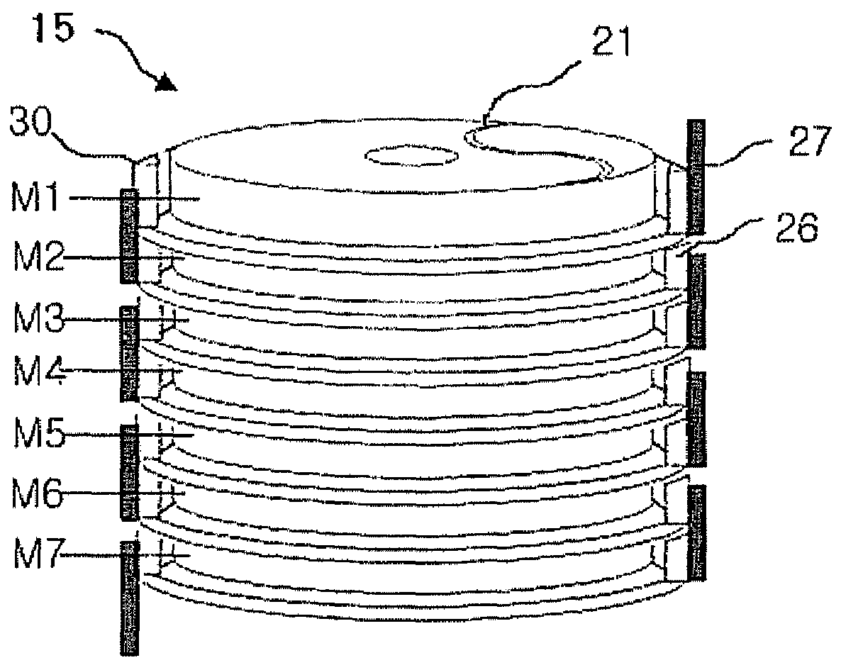
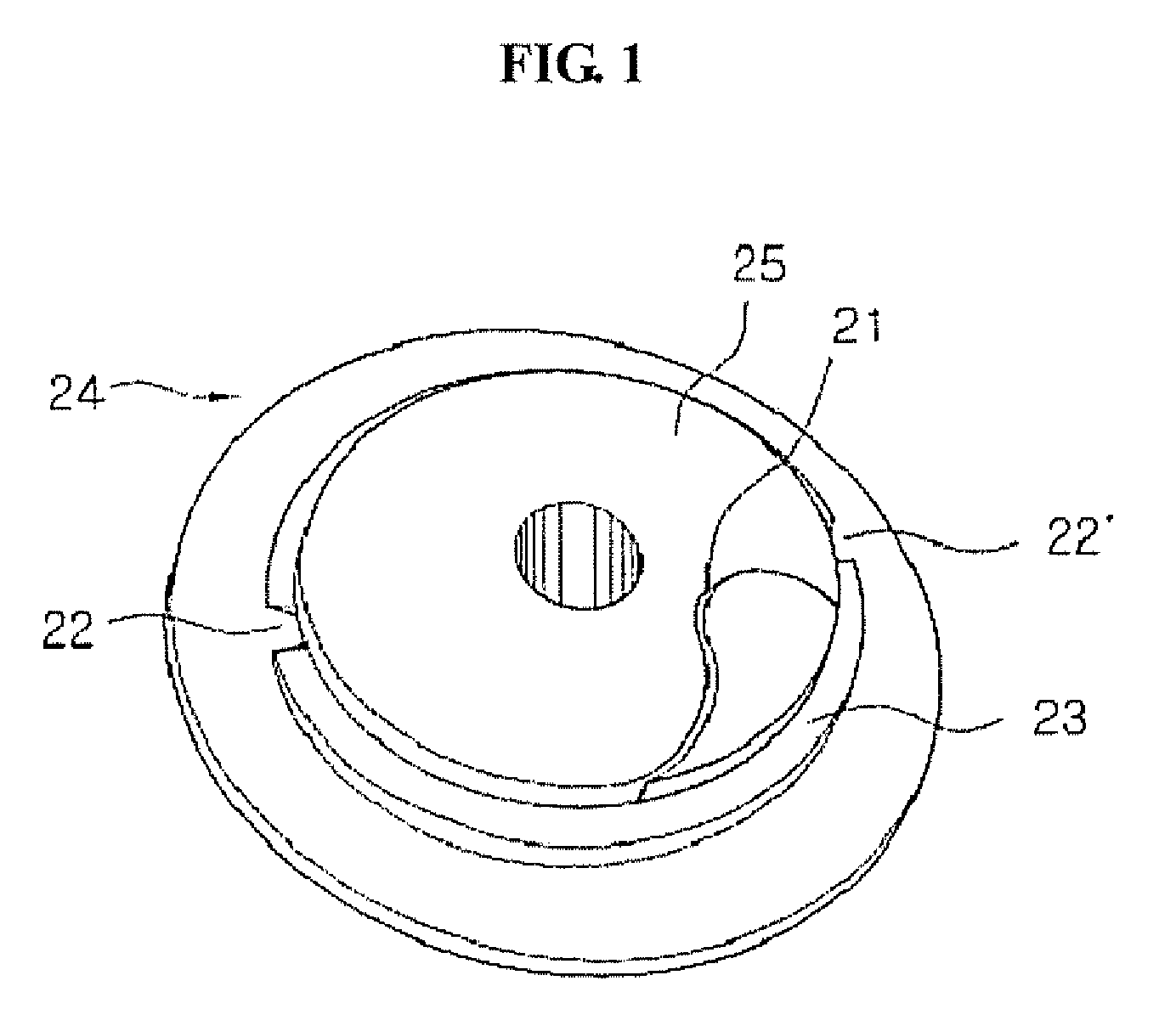
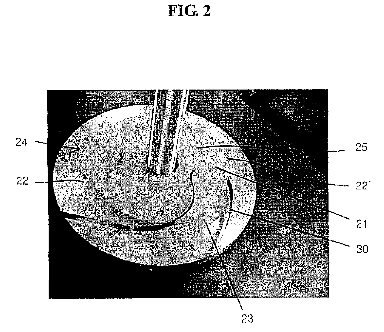
[0027]FIG. 1 is a perspective view of a bifilar winding bobbin of a fault current limiter according to the present invention. FIG. 2 is a photograph of a first superconducting wire fixed to the winding bobbin of FIG. 1. FIG. 3 is a photograph of a first metal block attached to the winding bobbin according to the present invention. FIG. 4 is a photograph of the coupling between non-inductivity winding modules according to the present invention. FIG. 5 is a perspective view of a pancake type current limiting module according to the present invention. FIG. 6 is a perspective view showing a solenoid type superconducting bypass reactor according to the present invention. FIG. 7 is a partially broken view showing the fault current l...


PUM


Abstract

A fault current limiter comprises a pancake type current limiting module, comprising at least two pancake type bifilar winding modules stacked and connected to each other in series, each of the bifilar winding modules having a bobbin, a first superconducting wire wound around the bobbin in a bifilar manner, and at least one pair of first metal blocks installed and fixed to the bobbin and attached to the first superconducting wire; and a superconducting bypass reactor that has the current limiting module disposed therein, and is connected in parallel with the current limiting module.

Description

CROSS-REFERENCE TO RELATED APPLICATION[0001]This application claims priority to and the benefit of Korean Patent Application No. 10-2006-0019821 filed with the Korean Intellectual Property Office on Mar. 2, 2006, the entire content of which is incorporated herein by reference.BACKGROUND OF THE INVENTION[0002]1. Field of the Invention[0003]The present invention relates generally to fault current limiters having superconducting bypass reactors for simultaneous quenching and, more particularly, to a fault current limiter having a superconducting bypass reactor for simultaneous quenching in which, when quenching occurs in a current limiting module, current is bypassed into a superconducting bypass reactor to generate a magnetic field that is evenly applied to the current limiting module provided in the bypass reactor. This causes simultaneous quenching, thus preventing multiple winding modules in the current limiting module from being damaged when voltage is concentrated in one winding ...

Claims


Application Information

Patent Timeline
Patent Type & Authority Patents(United States)
IPC IPC(8): H02H9/00
CPCH01L39/16H01F6/06H01F6/02H01F2006/001H10N60/30H02H9/023
Inventor PARK, DONG-KEUNAHN, MIN-CHOELYANG, SEONG-EUNKO, TAE-KUK
Owner IND ACADEMIC CORP FOUND YONSEI UNIV
Why Eureka
Try Eureka