
Power tool

a technology of power tools and torque limiters, which is applied in the direction of couplings, slip couplings, drilling machines, etc., to achieve the effect of improving the durability of a torque limiter in a power tool

Active Publication Date: 2009-09-22
MAKITA CORP
View PDF11 Cites 7 Cited by
  • Summary
  • Abstract
  • Description
  • Claims
  • Application Information

AI Technical Summary

Benefits of technology

Enhances the durability of power tools by reducing wear on the ball and driven flange through increased contact area and rolling movement, thereby extending the tool's operational life.

Problems solved by technology

Thus, local wear is caused and in this connection, further improvement is required in durability.

Method used


Image

  • Power tool
  • Power tool
  • Power tool

Examples


Embodiment Construction

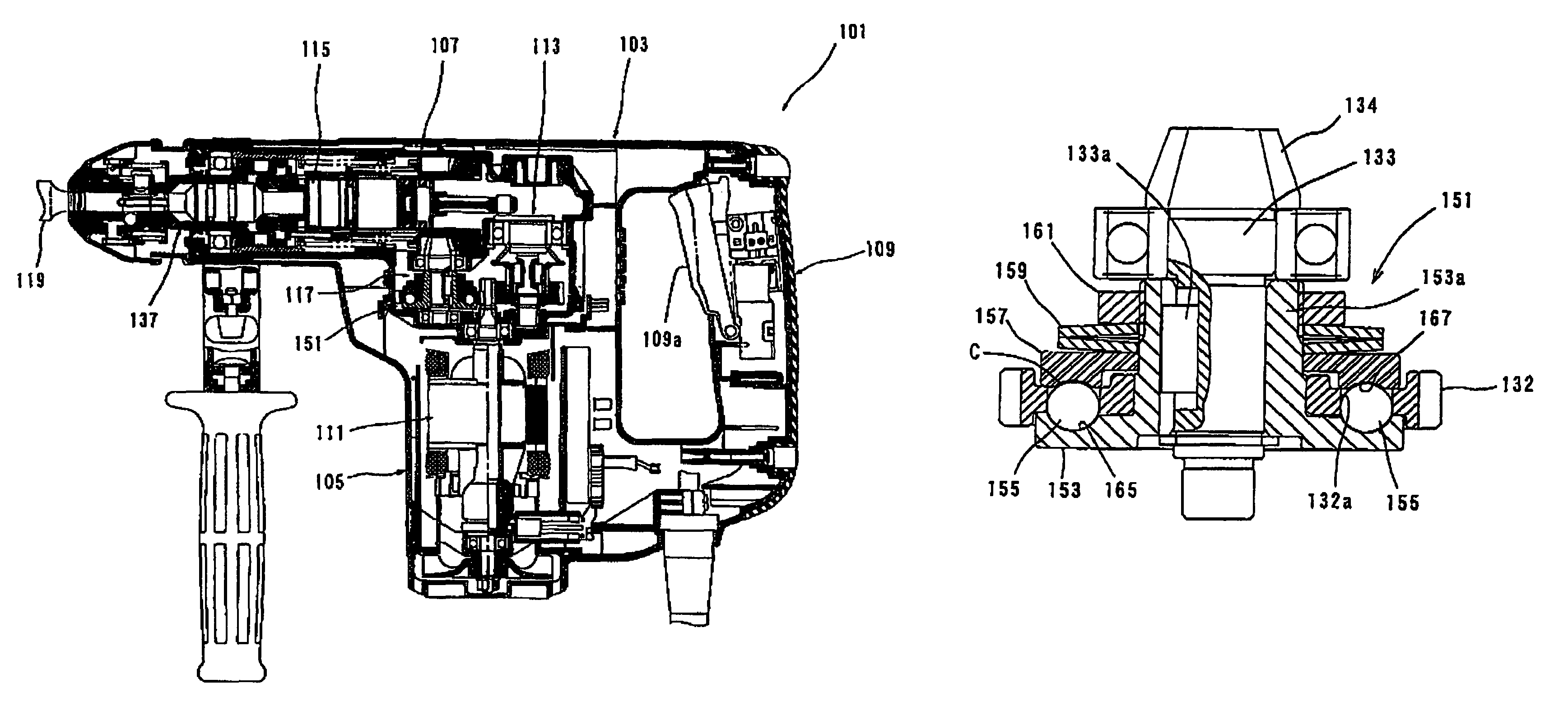
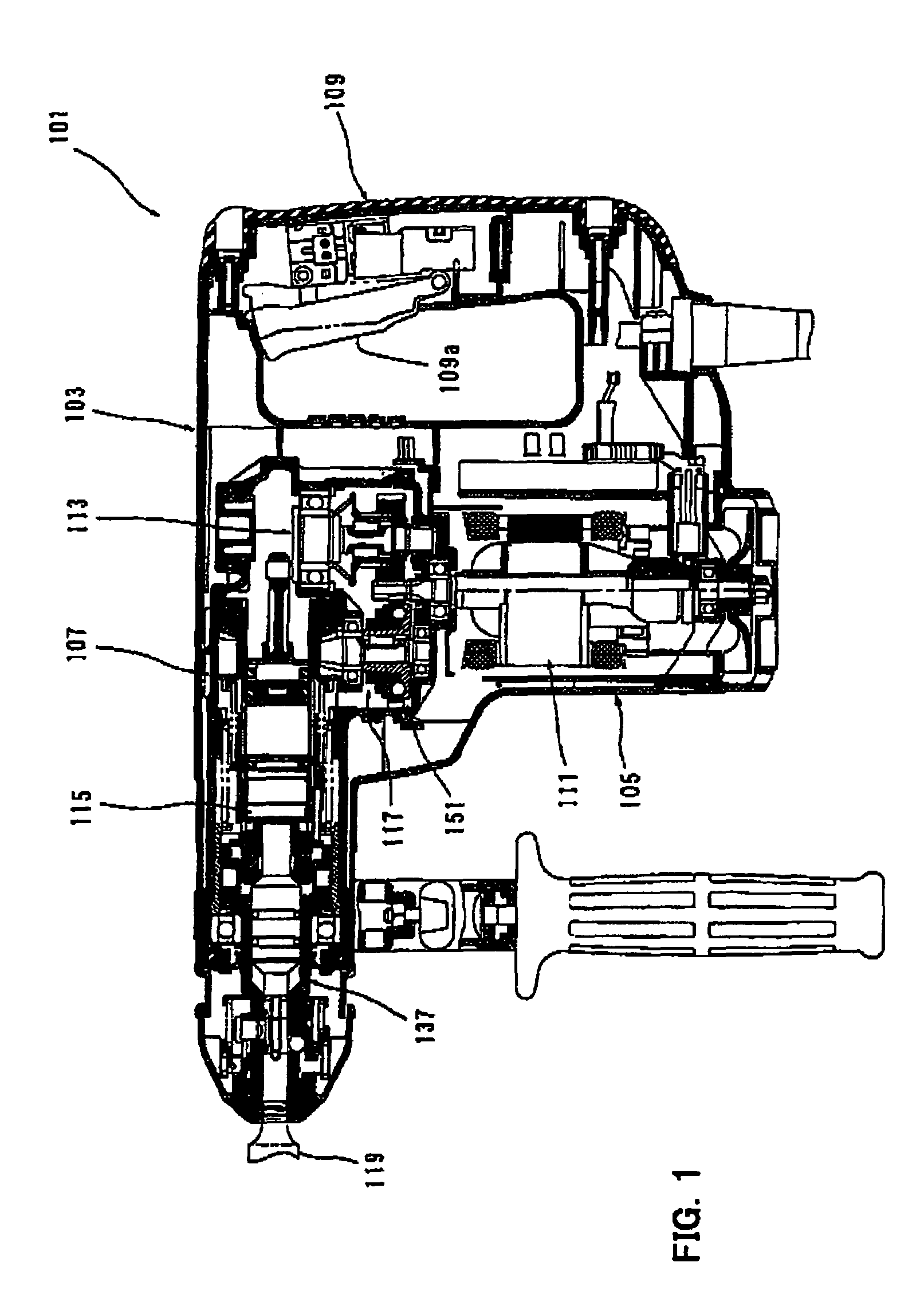
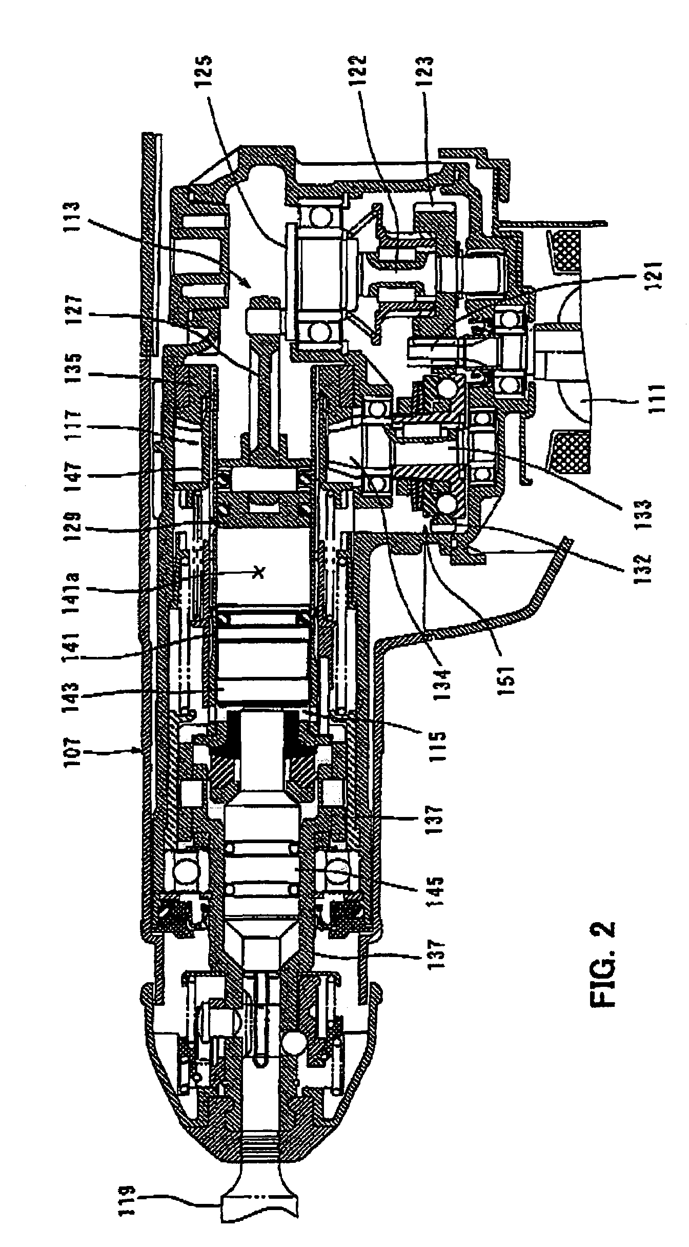
[0028]Each of the additional features and method steps disclosed above and below may be utilized separately or in conjunction with other features and method steps to provide and manufacture improved power tool and method for using such power tools and devices utilized therein. Representative example of present invention, which examples utilized many of these additional features and method step conjunction, will now be described in detail with reference to the drawing. This detailed description is merely intended to teach a person skilled in the art further details for practicing preferred aspects of the present teachings and is not intended to limit the scope of the invention. Only the claims define the scope of the claimed invention. Therefore, combinations of features and steps disclosed within the following detailed description may not be necessary to practice the invention in the broadest sense, and are instead taught merely to particularly describe some representative examples ...


PUM

PropertyMeasurementUnit
torqueaaaaaaaaaa
biasing forceaaaaaaaaaa
curvatureaaaaaaaaaa

Abstract

It is an object of the invention to provide an effective technique for improving the durability of a torque limiter utilized in a power tool. The object is achieved by a representative power tool comprising a tool bit, a driving mechanism and a torque limiter. The torque limiter includes first and second rotating members, a ball, a pressing member and an elastic member. The second rotating member includes a power transmitting region with a groove continuously formed from a deepest groove part to a shallowest groove part to allow torque transmission and a power transmission interrupted region with a groove shallower than the shallowest groove part of the power transmitting region to interrupts the torque transmission. According to this construction, when the ball is in the power transmitting region, the pressing member contacts the first rotating member and is held in a position in which the biasing force of the elastic member is prevented from acting upon the ball.

Description

BACKGROUND OF THE INVENTION[0001]1. Field of the Invention[0002]The present invention relates to a power tool having a tool bit that performs a predetermined operation by rotating on its axis and more particularly, to a power tool having a torque limiter that selectively interrupts transmission of torque to the tool bit.[0003]2. Description of the Related Art[0004]Japanese non-examined laid-open patent publication No. 9-57511 discloses a hammer drill having a torque limiter. The known torque limiter has a torque transmitting ball between a driving-side rotating member in the form of a driving gear and a driven-side rotating member in the form of a driven flange which are coaxially dispose The ball is held in a radial holding groove formed in the driven flange and engages with a cam of the driving gear in the circumferential direction so that the torque of the driving gear is transmitted to the driven flange. When the torque acting between the driving gear and the driven flange excee...

Claims


Application Information

Patent Timeline
Patent Type & Authority Patents(United States)
IPC IPC(8): F16D7/00
CPCB23B45/008B25B23/141B25D16/003F16D7/08B23B2260/0445B25D2211/068B25D2250/165B25D2250/321B25D2211/003
Inventor IKUTA, HIROKI
Owner MAKITA CORP
Learn More