
Centrifugal blower for air handling equipment

a centrifugal blower and air handling technology, which is applied in the direction of machines/engines, stators, liquid fuel engines, etc., can solve the problems of increasing the cost associated with providing products, and achieve the effects of improving the blower configuration, improving the blower efficiency, and reducing the acoustic emission of the blower

Inactive Publication Date: 2009-09-22
TRANE INT INC
View PDF12 Cites 25 Cited by
  • Summary
  • Abstract
  • Description
  • Claims
  • Application Information

AI Technical Summary

Benefits of technology

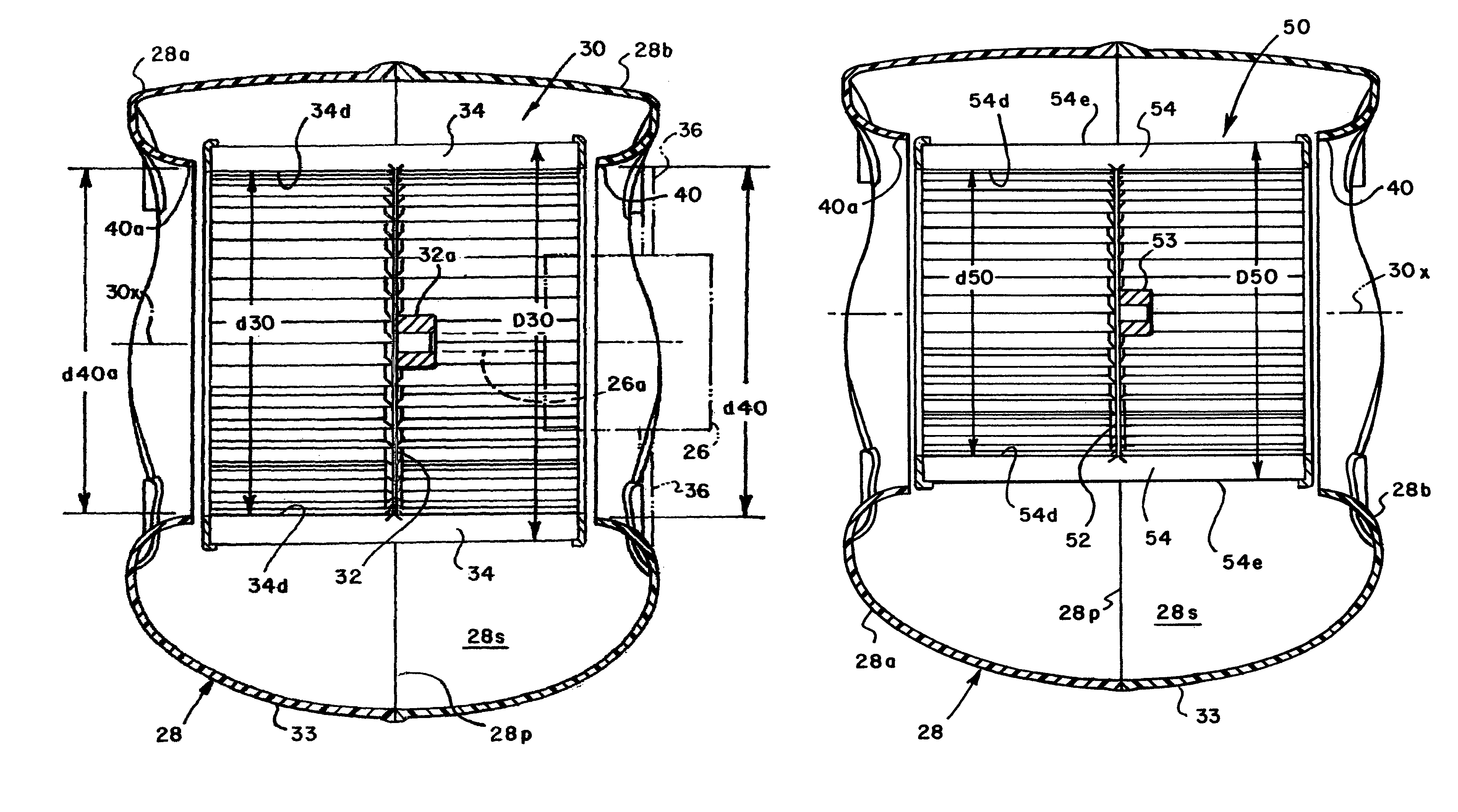
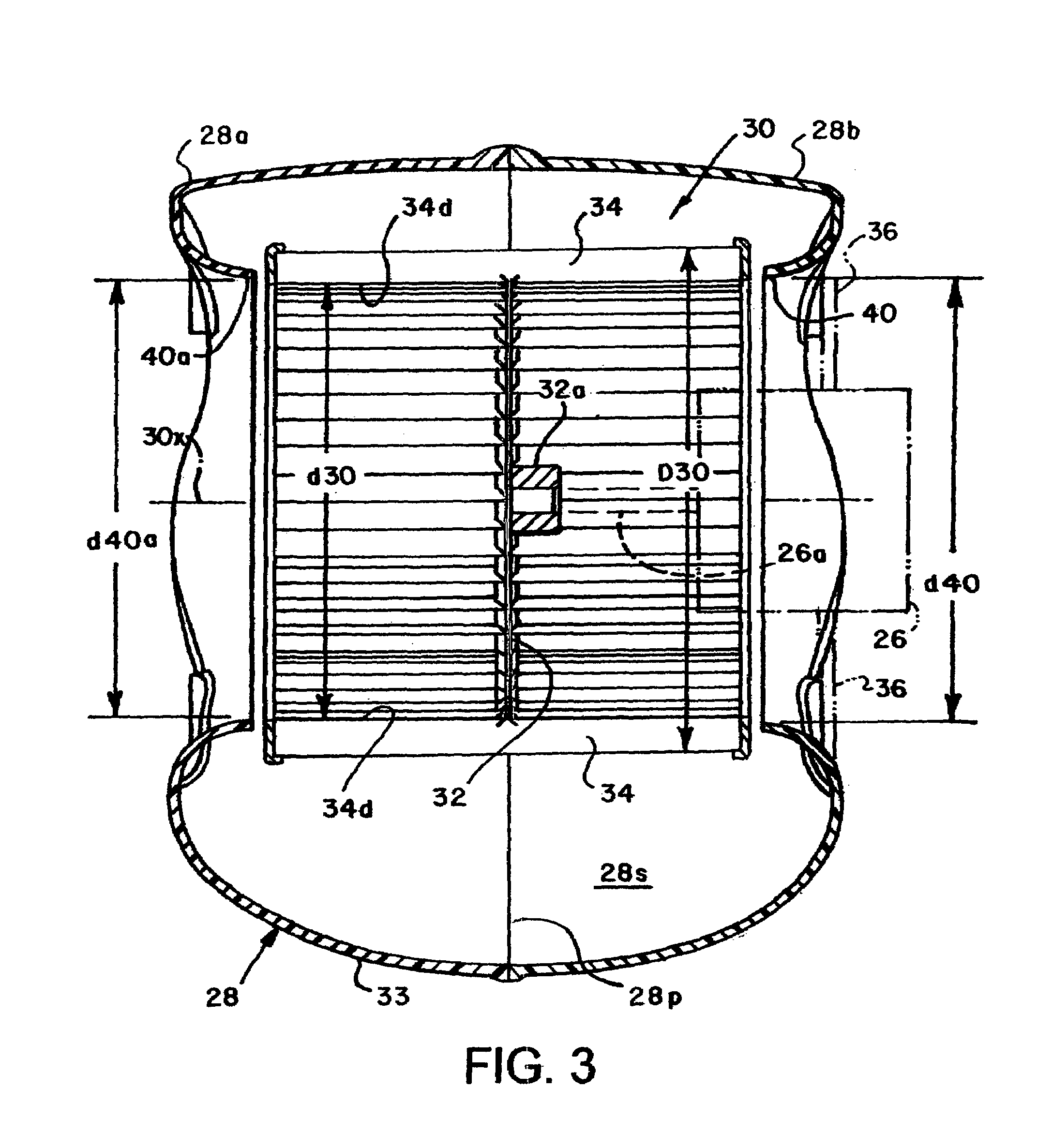
[0007]Still further, in accordance with the invention, a centrifugal air handling blower is provided wherein a blower housing having a somewhat spiral or scroll-like air flowpath configuration includes an improved blower wheel cutoff edge configuration having first and second ends and a midsection operable to accommodate a blower wheel or impeller of a selected range of outside diameters wherein the efficiency of the blower is improved, as compared with conventional centrifugal air handling blowers, and blower acoustic emissions are reduced for the same range of blower wheel diameters.
[0008]Accordingly, an improved blower configuration is provided by the invention wherein, for a particular size of scroll-like blower housing, a range of blower impeller sizes may be provided wherein such impellers have a particular range of diameters which may be used with the blower housing without reduction in efficiency or increase in noise generated through the use of impellers of various sizes. Still further, the combination of a scroll-like blower housing and range of blower impeller sizes in accordance with the invention provides for obtaining a predetermined air flow rate and discharge pressure required for a blower application at a rotational speed that corresponds to an efficient operating point for the blower drive motor. This flexibility is particularly advantageous for applications utilizing so-called PSC (permanent split capacitor) motors which have an efficiency peak at about ninety percent of synchronous speed. The efficiency of such motors tends to deteriorate at rotational speeds which deviate from the ninety percent of synchronous speed value.

Problems solved by technology

Of course, such a situation increases the costs associated with providing products to suit each blower application.

Method used


Image

  • Centrifugal blower for air handling equipment
  • Centrifugal blower for air handling equipment
  • Centrifugal blower for air handling equipment

Examples


Embodiment Construction

[0018]In the description which follows, like parts are marked throughout the specification and drawing with the same reference numerals, respectively. The drawing figures are not necessarily to scale and certain features may be shown exaggerated in scale or in somewhat generalized form in the interest of clarity and conciseness.

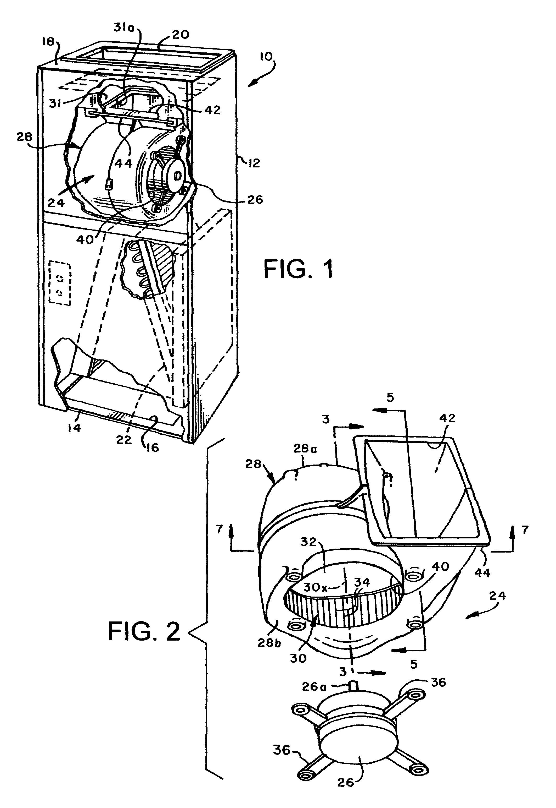
[0019]Referring to FIG. 1, there is illustrated a heating, ventilating and air conditioning unit (HVAC), generally designated by the numeral 10, characterized by a generally rectangular cabinet 12 having a bottom wall 14 defining an air inlet opening 16 and a top wall 18 defining an air outlet opening 20. The unit 10 may comprise a so-called air handler including an air conditioning evaporator coil 22 disposed therein in the flowpath of air passing from the inlet 16 to the outlet 20. An air handling blower in accordance with the invention is disposed in the cabinet 12 and generally designated by the numeral 24. The blower 24 includes a somewhat conventional e...


PUM


Abstract

An air handling blower for HVAC equipment includes a blower housing adapted to accommodate centrifugal impellers of selected inside and outside diameters of the impeller blades wherein the inside diameter of the largest diameter impeller accommodated by the housing is not less than the outside diameter of the smallest diameter impeller accommodated by the housing without loss of performance. The blower housing preferably has a continuously increasing cross-sectional airflow area for air being discharged from the blower and extending from a cutoff edge to an outlet.

Description

BACKGROUND OF THE INVENTION[0001]Motor driven centrifugal blowers for air handling equipment, such as heating, ventilating and air conditioning (HVAC) systems are well known. A typical air handling blower includes a scroll-like housing within which is mounted a centrifugal blower wheel or impeller of a selected diameter and axial length and wherein the housing is adapted or “sized” to operate efficiently with a particular blower wheel or impeller.[0002]However, there are many applications of air handling equipment wherein it is desirable to select the impeller size to accommodate a particular airflow requirement, impeller rotational speed and static or blower discharge pressure requirement, or a change in such requirements. Such performance requirements or desiderata in the equipment market may dictate that many different size blower wheels and associated blower housings be designed and fabricated to meet particular performance requirements of the blower application. Of course, such...

Claims


Application Information

Patent Timeline
Patent Type & Authority Patents(United States)
IPC IPC(8): F04D29/44
CPCF04D29/4226Y10S415/912
Inventor HANCOCK, STEPHEN S.
Owner TRANE INT INC
Learn More