Retrograde plunger delivery system

a technology of plunger and plunger, which is applied in the field of medical delivery devices, can solve problems such as patient harm, and achieve the effects of threatening patient outcomes and unnecessary patient risk

a technology of plunger and plunger, which is applied in the field of medical delivery devices, can solve problems such as patient harm, and achieve the effects of threatening patient outcomes and unnecessary patient risk

US7591822B2Inactive Publication Date: 2009-09-22BOSTON SCI SCIMED INC

Image

  • Retrograde plunger delivery system
  • Retrograde plunger delivery system
  • Retrograde plunger delivery system

Examples


Embodiment Construction

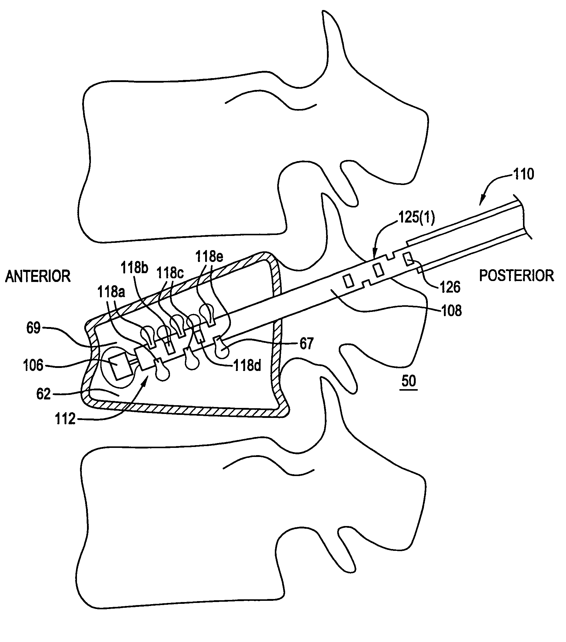
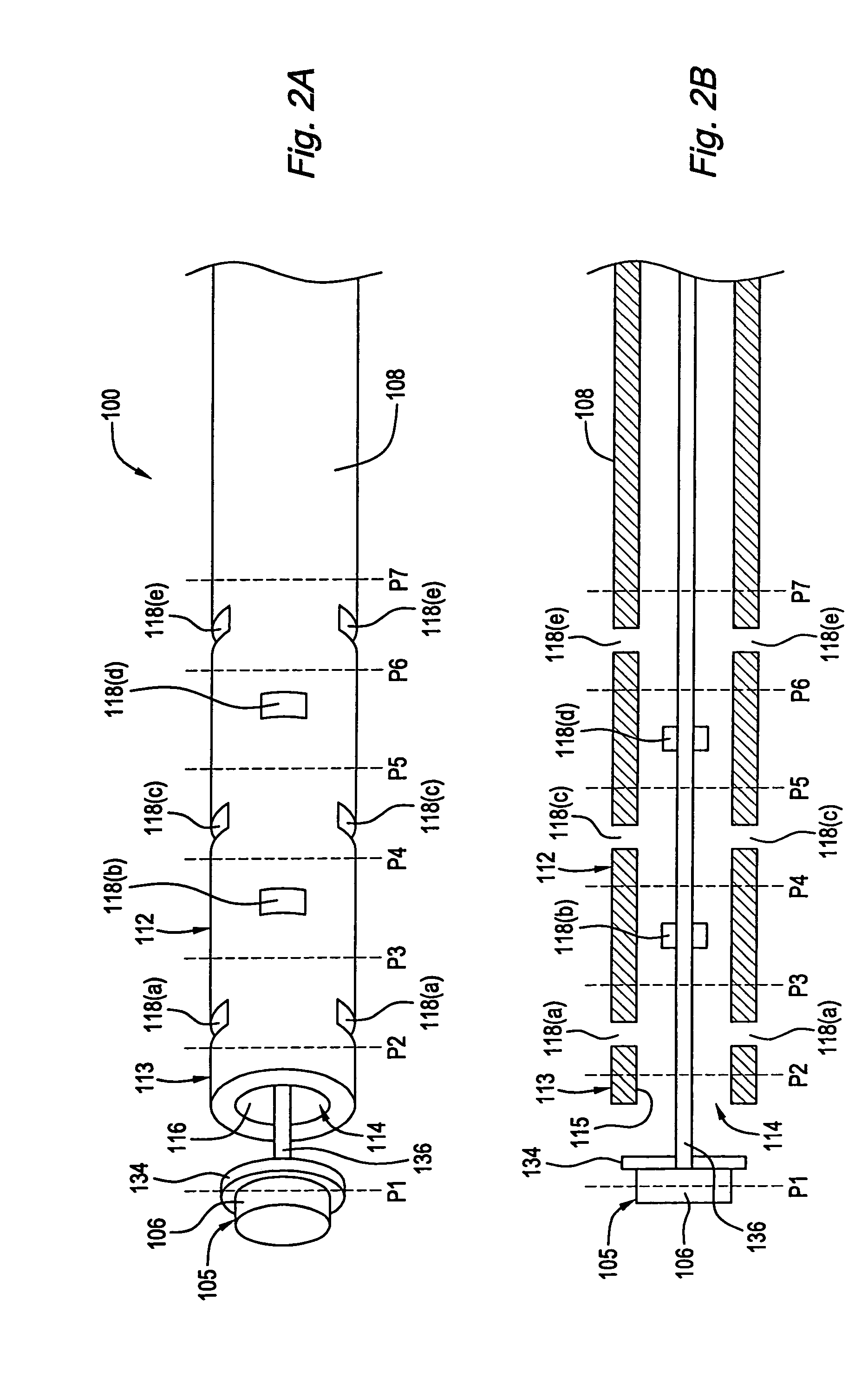
[0028]Referring to FIG. 2, a cannula 100 constructed in accordance with one preferred embodiment is illustrated. The cannula 100 generally includes a cannula body 108 with an associated slidable plunger assembly 105.

[0029]The cannula body 108 has a proximal end 110, a distal end 112, and a lumen 114 extending therethrough between the proximal and distal ends 110 and 112. In a preferred embodiment, the distal end 112 of the cannula body 108 is fenestrated. Specifically, the distal end 112 has a plurality of openings including a longitudinal opening 116 at the distal tip 113 of the cannula body 108 and a plurality of axially spaced transverse openings 118 proximal to the distal tip 113. The longitudinal opening 116 and the plurality of transverse openings 118 are in fluid communication with the lumen 114 of the cannula body 108. As illustrated in FIGS. 2A and 2B, the transverse openings 118 are arranged in axially spaced groups of openings 118(a)-(e). Each of the transverse opening gr...


PUM


Abstract

Cannulas are provided for delivering therapeutic material to a treatment site. The cannula includes a cannula body with a plurality of openings at the distal end, including a longitudinal opening and a plurality of transverse openings that are axially spaced from each other. The cannula also includes a plunger that is configured to be slidably disposed within the cannula lumen. When the plunger is proximally displaced in the cannula lumen, the plunger seals the distal end and deflects the therapeutic material out the transverse openings. As the plunger is proximally displaced within the lumen, the therapeutic material is forced to perfuse out transverse openings located proximal of the plunger position. In one embodiment, the plunger includes an additional pliable sealable member. In another embodiment, the distal end of the cannula body may be implanted by separating the distal end from the cannula body.

Description

RELATED APPLICATION DATA[0001]This application is a continuation of U.S. patent application Ser. No. 10 / 183,220, now U.S. Pat. No. 6,730,095, filed on Jun. 26, 2002, the priority of which is claimed under 35 U.S.C. §120, and the contents of which is incorporated herein by reference in its entirety, as though set forth in full.FIELD OF THE INVENTION[0002]This invention relates to medical delivery devices, and in particular, to cannula needle or sheath systems for directed delivery of biomaterials.BACKGROUND[0003]Numerous bone conditions or spinal injury can cause painful collapse of vertebral bodies, including osteopenia (osteoporosis), vertebral hemangiomas, multiple myeloma, necorotic lesions (Kummel's Disease, Avascular Necrosis), metastatic disease and complications from steroid and non-steroidal anti-inflammatory drug (NSAID) use. Osteoporosis is a systemic, progressive and chronic disease that is usually characterized by low bone mineral density, deterioration of bony architect...

Claims


Application Information

Patent Timeline
22 Sep 2009
Publication
US7591822B2
IPC
A61B17/56; A61B17/88; A61M25/00
CPC
A61B17/7098; A61B17/8811; A61M2210/02; A61M25/007; A61M25/0069
Inventors
OLSON, JR., STANLEY W.; JANSEN, LEX P.