X-ray imaging with continuously variable zoom and lateral relative displacement of the source

a technology of x-ray imaging and lateral relative displacement, which is applied in the direction of radiation/particle handling, nuclear engineering, and diaphragm/collimeter handling, etc., can solve the problems of resolution loss in design distance, and achieve the effect of controlling the area resolution of x-ray imaging

Active Publication Date: 2009-09-22
AMERICAN SCI & ENG INC
View PDF55 Cites 67 Cited by
  • Summary
  • Abstract
  • Description
  • Claims
  • Application Information

AI Technical Summary

Benefits of technology

[0008]In accordance with preferred embodiments of the present invention, methods and apparatus are provided for varying the field-of-view of imaging systems that have a source of penetrating radiation and a first and second aperture disposed in the path of the penetrating radiation. The field of view is varied, in accordance with preferred embodiments of the invention, by repositioning the source of radiation with respect to the apertures shaping the beam. As a result of varying the FOV, the areal resolution of x-ray imaging can be controlled. In particular, a translator is provided for repositioning the source relative to the first aperture transversely with respect to the path of emitted radiation.

Problems solved by technology

An object at a distance shorter than the design distance is “cut-off”, while an object more distant that the design distance suffers resolution loss.

Method used


Image

  • X-ray imaging with continuously variable zoom and lateral relative displacement of the source
  • X-ray imaging with continuously variable zoom and lateral relative displacement of the source
  • X-ray imaging with continuously variable zoom and lateral relative displacement of the source

Examples


embodiment 50

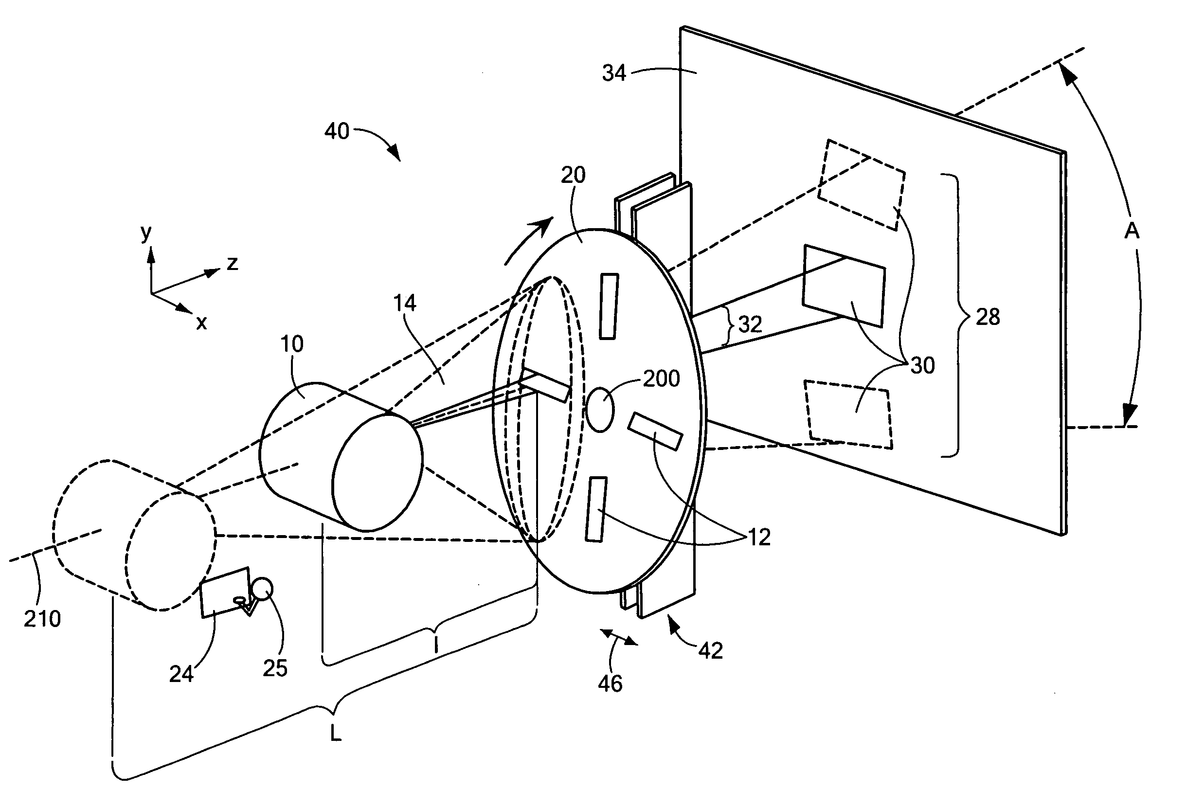
[0025]Field-of-view A (defined by the view, from source 10, of the angular extent of the image 28 that is comprised by the transitory illuminating spots 30 of the scanning apertures 12) is reduced by moving the source 10 away from the wheel 20 as shown in FIG. 4 (and, therefore, increasing the separation between the source and the wheel from L1 to L2), the output flux of penetrating radiation in a scanning beam 32 (which may have any specified cross-sectional shape, within the scope of the present invention), incident on the object under inspection OUI 34 at any instant of time, decreases as well. This is because a progressively smaller portion of wide-angle radiation pattern of the source 10 is being subtended by the one of the apertures 12. To improve grainy and statistically poor images that may result from reduced flux leading to insufficient irradiation of the object, or, otherwise, to adjust resolution, an embodiment 50 of the device of the invention, shown in FIG. 5 in front ...

embodiment 80

[0027]Embodiments of the current invention may provide advantages over the prior art by moving an x-ray source in the direction transverse to the optical axis of the system. In the embodiment 80 of FIG. 8, for example, the source 10 is displaced perpendicularly to the z-axis from the position j to another position jj, as indicated by an arrow 62. A beam formed by the aperture(s) 12 of the wheel 20 and the collimator 22, tracks the motion of the source, as represented by the respective change in the orientation of the marginal ray from 64,j to 64,jj, and appropriately scans the target 66 in −x direction. Combined with scanning the radiation pattern in xy-plane due to rotation of the wheel 20 about axle 200, such transverse repositioning 62 of the source 10 generates a raster scan of the target 66. Although particularly suited for distant imaging, the use of this embodiment is not limited to that application.

[0028]In alternative embodiments of the present invention, the integration ti...


PUM


Abstract

An inspection system based on penetrating radiation in which the field of view of a scan may be varied. First and second primary limiting apertures are provided for interposition between a source of penetrating radiation and an inspected object. This allows for significantly increasing the flux of penetrating radiation on this narrowed region of interest, thereby advantageously improving detectability. The relative position of the source with respect to either the first or the second aperture may be varied, in a direction either along, or transverse to, a normal to the aperture.

Description

[0001]The present application claims priority from U.S. Provisional Patent Application Ser. No. 60 / 982,099, filed Oct. 23, 2007, which is incorporated herein by reference.TECHNICAL FIELD[0002]The present invention relates to methods and systems for controlling the spatial resolution of imaging systems, and specifically to controlling the spatial resolution of such imaging systems by moving a source of radiation relative to an aperture.BACKGROUND OF THE INVENTION[0003]The present application contains subject matter related to that of US Published Patent Application US-2006-0245547, filed Mar. 21, 2006, which is incorporated herein by reference.[0004]Current x-ray imaging systems typically make use of penetrating radiation characterized by a relatively wide-angle pattern that emerges from an x-ray generator such as an x-ray tube. Referring to the prior art configuration depicted in FIG. 1, the angular field of view A of the x-ray beam is conventionally determined by the angular extent...

Claims


Application Information

Patent Timeline
Patent Type & Authority Patents(United States)
IPC IPC(8): G21K1/04
CPCG21K1/043G21K1/04
Inventor ROTHSCHILD, PETER J.
Owner AMERICAN SCI & ENG INC
Why Eureka
Try Eureka