Automated timer and setpoint selection for pneumatic test equipment

a pneumatic test and automatic timer technology, applied in the direction of measuring devices, instruments, structural/machine measurement, etc., can solve the problems of rapid testing compromise, reduced pressure within the unit after the unit, and difficulty in practical application

Active Publication Date: 2009-09-29
CINCINNATI TEST SYST
View PDF20 Cites 90 Cited by
  • Summary
  • Abstract
  • Description
  • Claims
  • Application Information

AI Technical Summary

Problems solved by technology

While this method is an relatively straightforward to describe, its implementation in practical examples is fraught with the number of difficulties.
Unfortunately, rapid testing compromises the objective of obtaining a stabilized pressure within the unit prior to initiating a leakage test on the unit.
First, the rapid influx of pressurized gas into the unit compresses the gas within the UUT, which causes the gas to release heat to the UUT, which then cools, causing a reduction of pressure within the unit after the unit has been filled.
However, once the unit is disconnected from the pressurized source, cooling of the gas within the unit will cause a pressure drop which can be easily confused with the pressure drop that is caused by leakage.
A second difficulty arises from the fact that all units, including metal fluid carrying units, are subject to expansion and stretch when pressurized.
Too short of a test period might permit a leaking unit to pass through undetected, or force the use of a target pressure that rejects leak-free units that have a particularly low stabilized pressure.
Unfortunately, this method typically produces a less than optimum timing for the pressurization cycle because portions of the cycle are often made longer than is necessary to achieve sufficient stability of the testing process for an effective test.

Method used


Image

  • Automated timer and setpoint selection for pneumatic test equipment
  • Automated timer and setpoint selection for pneumatic test equipment
  • Automated timer and setpoint selection for pneumatic test equipment

Examples


Embodiment Construction

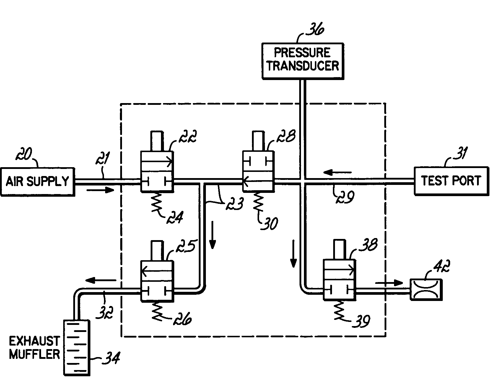
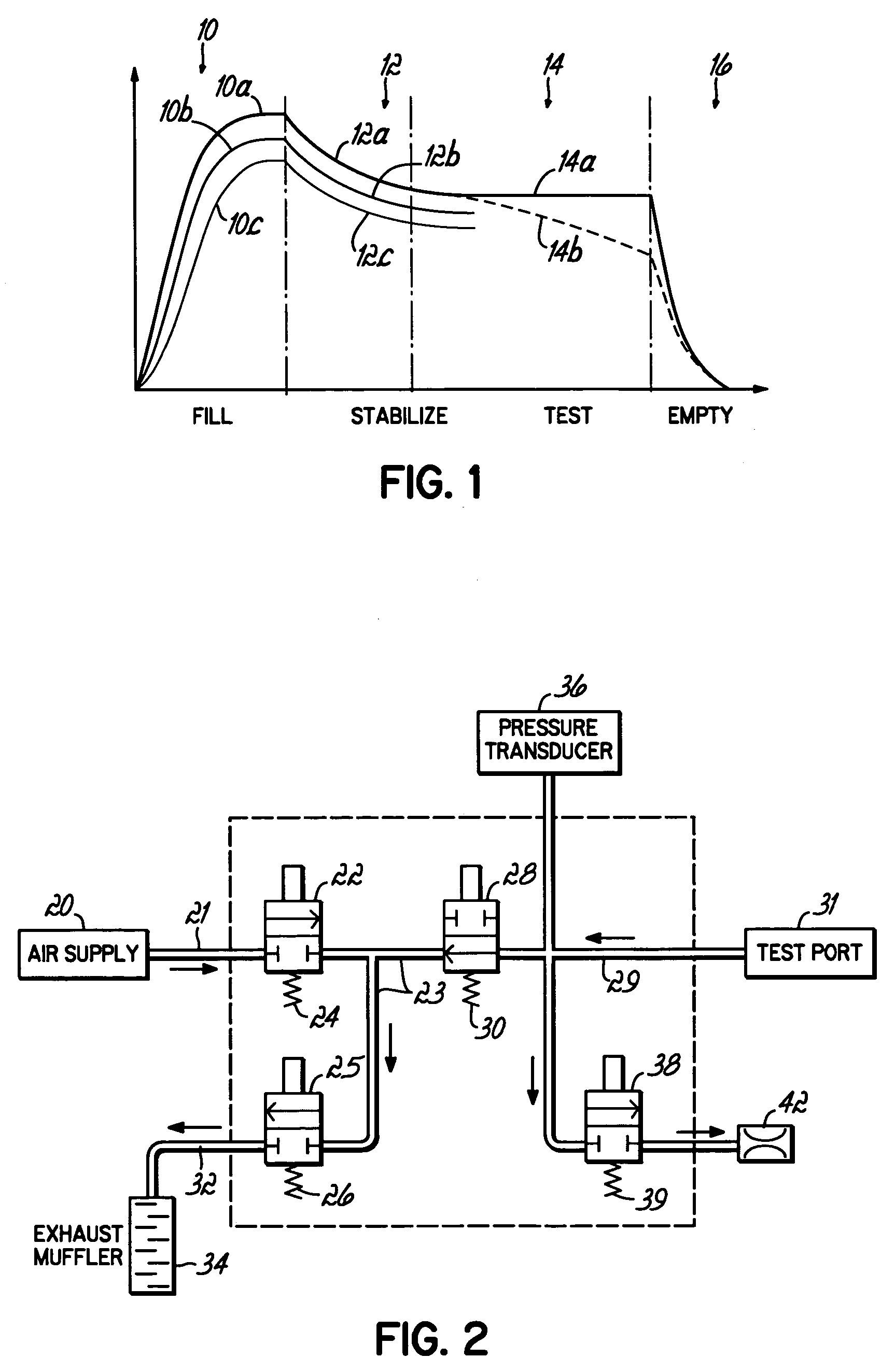
[0029]Referring now to FIG. 2, a testing platform for performing pneumatic testing of parts is illustrated. This testing platform includes an air supply 20 providing air pressurized to a pressure of, e.g., 60-130 pounds per square inch. This air supply is coupled to a fluid line 21 connected to a two-way normally closed valve 22. Normally closed valve 22, as illustrated, will normally isolate fluid line 21 from fluid line 23 unless a control signal is delivered to the valve 22 via connection 24.

[0030]Fluid line 23 connects pressurized air from valve 22 and supply 20 to normally closed two-way valve 25 and normally open two-way valve 28. Normally open valve 28 connects between fluid line 23 and fluid line 29 and permits free flow from fluid line 29 to fluid line 23 but will block flow from fluid line 23 to fluid line 29 unless actuated by a control signal delivered to input 30. The fluid line 29 is connected to the test port 31 to which the unit under test is attached.

[0031]To perfor...


PUM


Abstract

A fill time and stabilize and measurement time are determined for a pneumatic testing procedure. The fill time is computed by identifying, in the filling of a sample unit, a time when a substantial portion of variations of a measured variable (due to stabilization) are completed. The stabilize and measurement time is determined by comparison of the measurement variable behavior when filling sample unit(s) that do not leak, to the measurement variable behaviors when filling a sample unit that is in communication with an orifice simulating a leak. A measurement performance factor may be computed from this data at each of several possible times after a unit is filled. A gauge repeatability factor may be computed based on variance of nonleaking units at each possible time, compared to the variable change made on a sample unit when coupled to a leak-simulating orifice. Either factor may be used to select a stabilize and measurement time.

Description

FIELD OF THE INVENTION[0001]The present invention relates to pneumatic testing of fluid or gas carrying components such as automobile intake manifolds, fuel rails, refrigerant lines and the like.BACKGROUND OF THE INVENTION[0002]In many applications, fluid or gas carrying parts form critical components of a system. For example, in an automobile, fluid carrying parts couple the vehicle fuel supply to the engine intake and must be entirely free of leaks to prevent fuel spillage and a potentially dangerous condition. In a similar way, refrigerant carrying lines in a home air-conditioning system must be free of leaks so that refrigerant is unable to escape from the cooling system causing an air conditioning failure. The criticality of these parts mandates, in some instances, 100% testing of manufactured parts to verify the absence of leaks therein.[0003]Pneumatic testing of a fluid carrying part or “unit under test” (UUT) typically involves filling the unit with gas at a specified target...

Claims


Application Information

Patent Timeline
Patent Type & Authority Patents(United States)
IPC IPC(8): G01M3/02
CPCG01M3/2815
Inventor FAZEKAS, JONATHAN MARK
Owner CINCINNATI TEST SYST
Why Eureka
Try Eureka