
Bicycle lighting device

a technology for lighting devices and bicycles, applied in lighting and heating apparatus, cycle equipment, instruments, etc., can solve the problems of difficult attachment and detachment of lighting devices to and from handlebars, unmaintenable fastened state, etc., and achieve the effect of not readily rotating, easy attachment and detachment, and not easily rotated

Inactive Publication Date: 2009-09-29
SHIMANO INC
View PDF15 Cites 15 Cited by
  • Summary
  • Abstract
  • Description
  • Claims
  • Application Information

AI Technical Summary

Benefits of technology

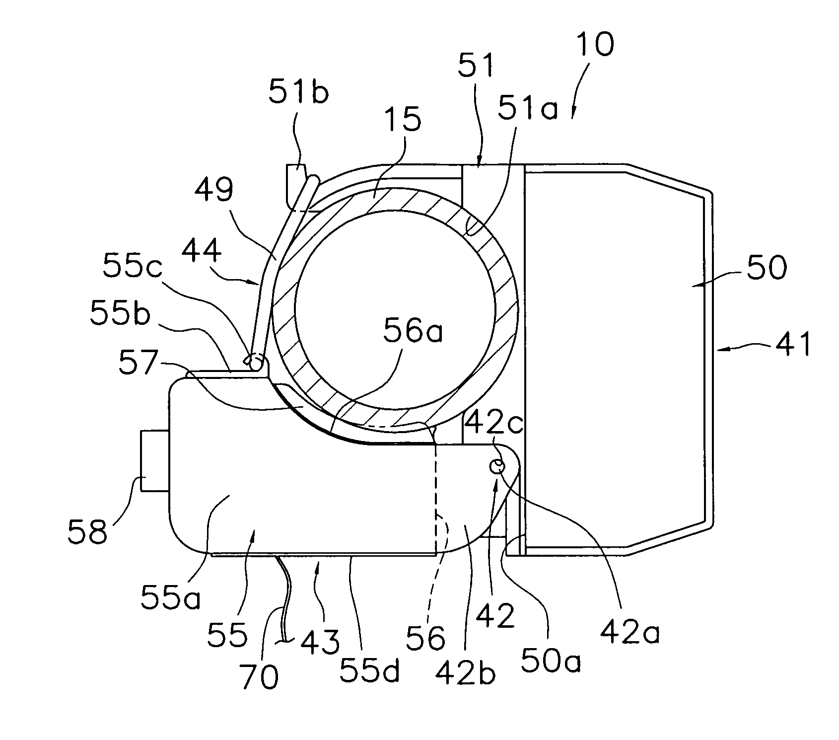
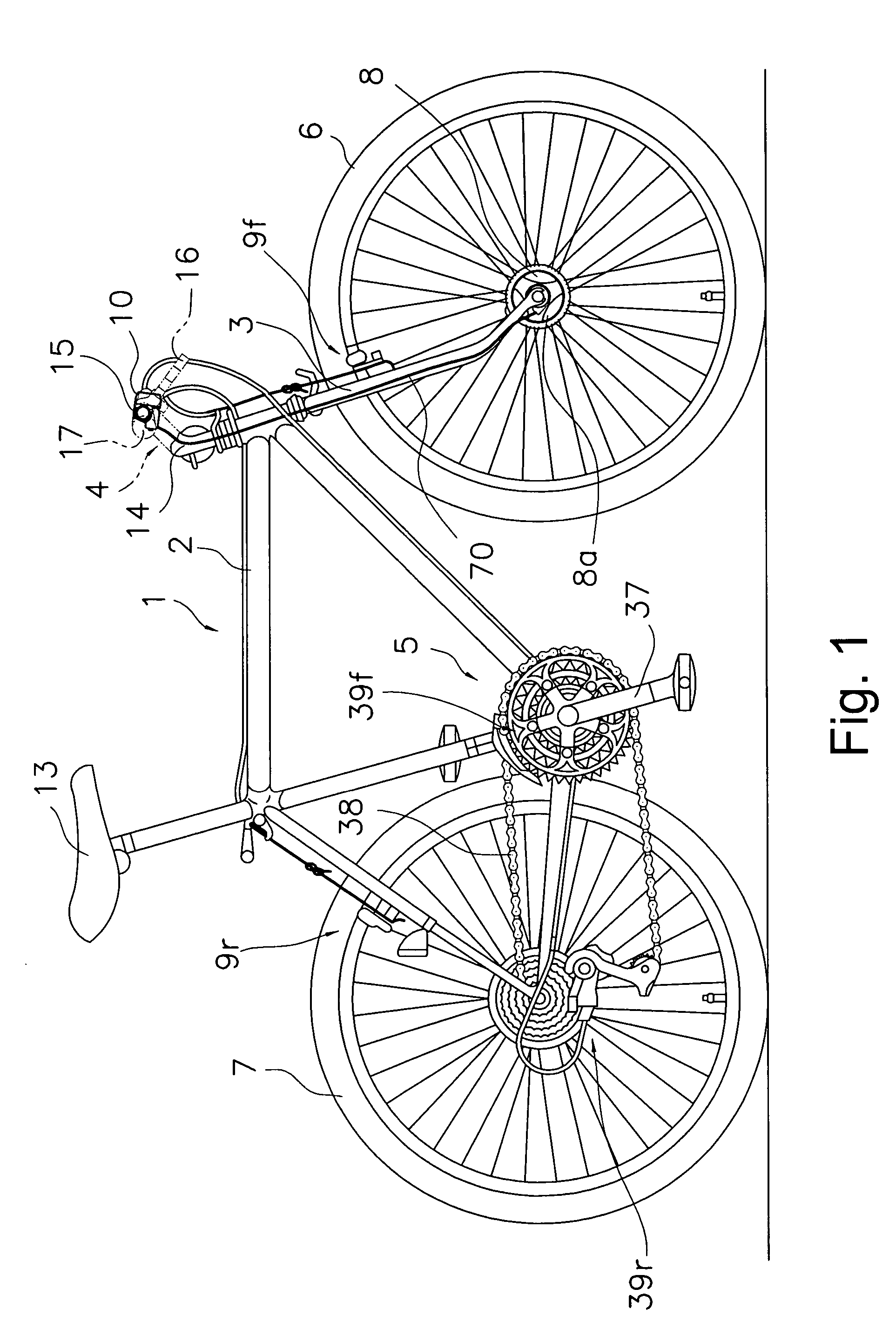
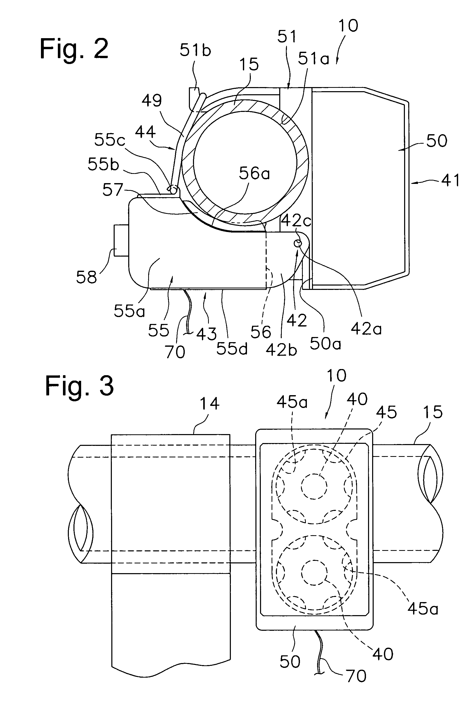
The present invention provides a bicycle lighting device that can be easily attached and detached to a bicycle, while also preventing the lighting device from rotating readily when attached. The lighting device includes a lamp case and a control case that are designed to pinch the handlebar or other portion of the bicycle, with a mounting unit that draws the lamp case and control case towards each other. The lighting device is mounted with a small fastening force, making it easy to attach and detach with a small amount of force. The lighting device also includes a hinge that allows for easy adjustment of the lighting angle, and a recessed mating surface for better contact with the handlebar. Additionally, the lighting device includes an electric power input part for receiving electric power from an alternating-current electric generator installed on the bicycle, and a control circuit with a rectifier circuit for converting the electric power. These features make the lighting device more convenient, easy to use, and prevent interference with other accessories.

Problems solved by technology

Consequently, when a rotational moment is large or when the elastic band does not have a strong fastening force, there is a possibility that a fastened state will not be maintainable and the main body will rotate due to vibrations or the like.
Conversely, if such a conventional lighting device is fastened securely by setting the elastic band such that it applies a strong force against the handlebar toward the recessed part, then the lighting device will be difficult to attach and detach to and from the handlebar.

Method used


Image

  • Bicycle lighting device
  • Bicycle lighting device
  • Bicycle lighting device

Examples


second embodiment

[0063]Referring now to FIG. 8, a control circuit 160 in accordance with a second embodiment will now be explained. In view of the similarity between the first and second embodiments, the parts of the second embodiment that are identical to the parts of the first embodiment will be given the same reference numerals as the parts of the first embodiment. Moreover, the descriptions of the parts of the second embodiment that are identical to the parts of the first embodiment may be omitted for the sake of brevity.

[0064]The control circuit 160 is basically the same as the control circuit 60 of the first embodiment except that, an electric energy storage element 73 is provided in the control circuit 160. The electric energy storage element 73 is connected in parallel with the full-wave rectifier circuit 71 within the control circuit 160. The electric energy storage element 73 is preferably a secondary battery, such as a rechargeable lithium ion battery, or a large capacity capacitor, such ...


PUM


Abstract

A bicycle lighting device configured to be mounted to a bicycle includes a lamp case, a control case and a mounting unit. The lamp case has a light emitting diode arranged therein. The control case is connected to the lamp case by a hinge. The control case is configured to clamp onto a handlebar. A control circuit for controlling the light emitting diode is installed inside the control case. The mounting unit is for attaching the lamp case and the control case to the handlebar in such a fashion that the lamp case and the control case are drawn close together.

Description

CROSS-REFERENCE TO RELATED APPLICATIONS[0001]This application claims priority under 35 U.S.C. § 119 to Japanese Patent Application No. 2005-178440. The entire disclosure of Japanese Patent Application No. 2005-178440 is hereby incorporated herein by reference.BACKGROUND OF THE INVENTION[0002]1. Field of the Invention[0003]This invention generally relates to a bicycle lighting device. More specifically, the present invention relates to a bicycle lighting device that is well suited for use as a headlamp for a bicycle.[0004]2. Background Information[0005]Bicycling is becoming an increasingly more popular form of recreation as well as a means of transportation. Moreover, bicycling has become a very popular competitive sport for both amateurs and professionals. Whether the bicycle is used for recreation, transportation or competition, the bicycle industry is constantly improving the various components of the bicycle. For example, bicycle lighting devices have been extensively redesigned ...

Claims


Application Information

Patent Timeline
Patent Type & Authority Patents(United States)
IPC IPC(8): B62J6/00B62J11/19
CPCB62J6/02B62J6/003B62J6/015B62J6/029B62J6/03
Inventor OKAJIMA, SHINPEIGOTO, MASASHI
Owner SHIMANO INC
Learn More