Gas/liquid separator

a technology of separator and liquid, applied in the direction of separation process, vortex flow apparatus, dispersed particle separation, etc., to achieve the effect of preventing re-entrainment and preventing re-entrainment of liquid

Inactive Publication Date: 2009-09-29
SHELL OIL CO
View PDF29 Cites 55 Cited by
  • Summary
  • Abstract
  • Description
  • Claims
  • Application Information

AI Technical Summary

Benefits of technology

[0021]Applicant has found that by arranging a liquid collection promoter tray the re-entrainment of liquid in gas close to the outlet of the primary separator is reduced, and that the accumulation of liquid in the liquid collection space is improved. Without wishing to be bound by the following explanation, Applicant believes that the beneficial effect of the liquid collection promoter tray is caused by one or both of the following mechanisms. First, the receiving area of the tray provides a surface for the liquid droplets from the space underneath the vane inlet device to settle and to coalesce, which liquid is then passed towards the liquid collection space. Second, the liquid collection promoter tray at least partially shields the liquid collection space from the high gas velocities at the outlet of the (primary) separation device, thereby creating a space immediately above the liquid collection space where fluid velocities are lower to help the liquid to settle and to prevent re-entrainment.
[0022]The liquid collection promoter tray is advantageously arranged such that it optically closes the cross-section of the vessel when being looked at from the gas / liquid separator in downward direction. In this way the maximum liquid receiving area is provided for liquid to impinge and coalesce upon, and the space below the liquid collection promoter tray is shielded from the highest gas velocities.
[0023]In a particularly advantageous embodiment the liquid collection promoter tray is formed by an assembly of tilted plates. When these plates are arranged in an overlapping manner, an optically closed tray can be obtained which leaves relatively large passages between the plates through which liquid can flow downwardly and through which gas can pass. However, the tray represents a flow restriction for gas flowing vertically downward in the vessel. Gas passing through the tray must have a horizontal velocity component. In effect, the exchange of gas between the spaces immediately above and below the tray will be reduced, and the gas velocities in the space below will be considerably smaller than when no liquid collection promoter tray is arranged.

Problems solved by technology

However, the tray represents a flow restriction for gas flowing vertically downward in the vessel.

Method used


Image

  • Gas/liquid separator
  • Gas/liquid separator

Examples


Embodiment Construction

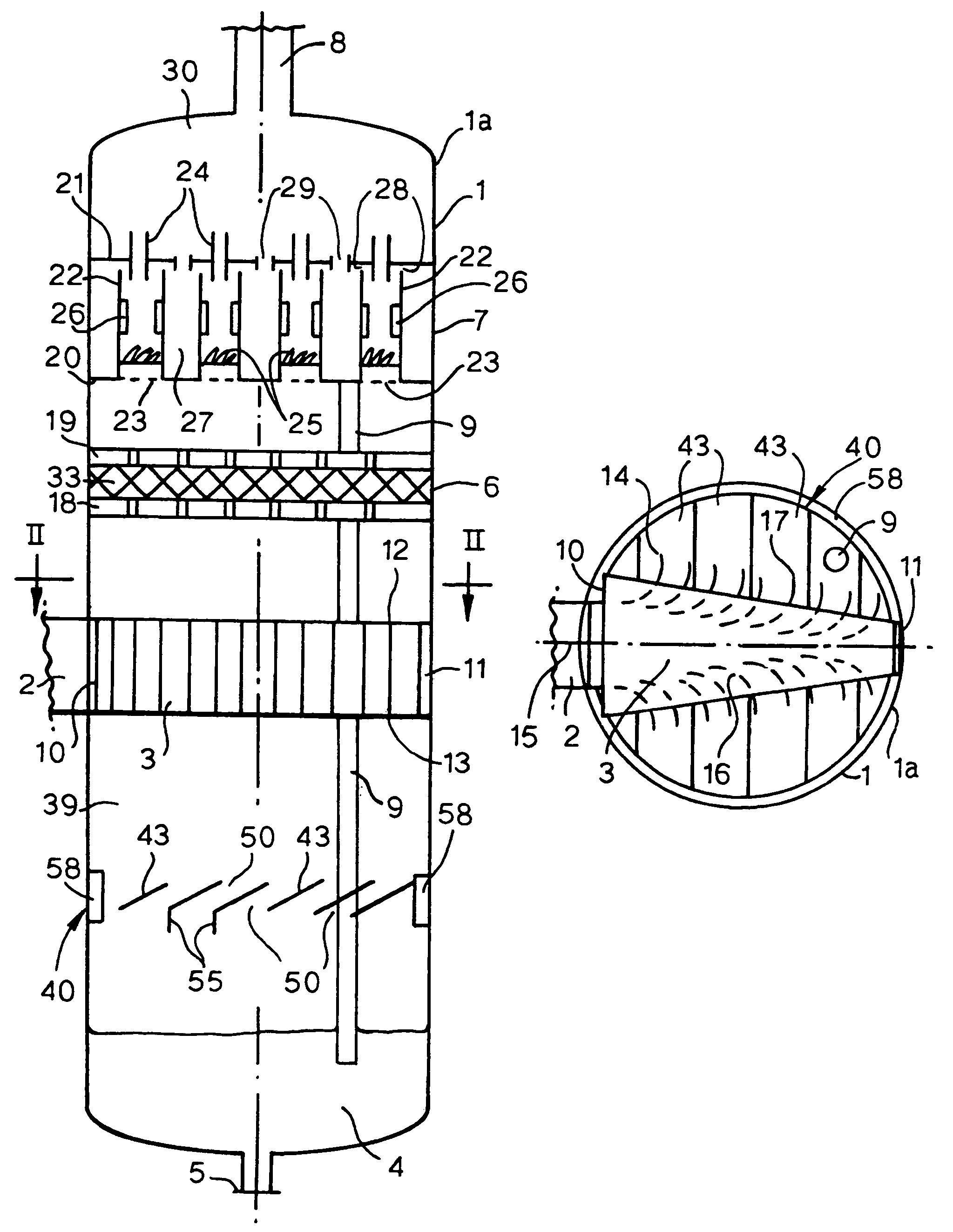
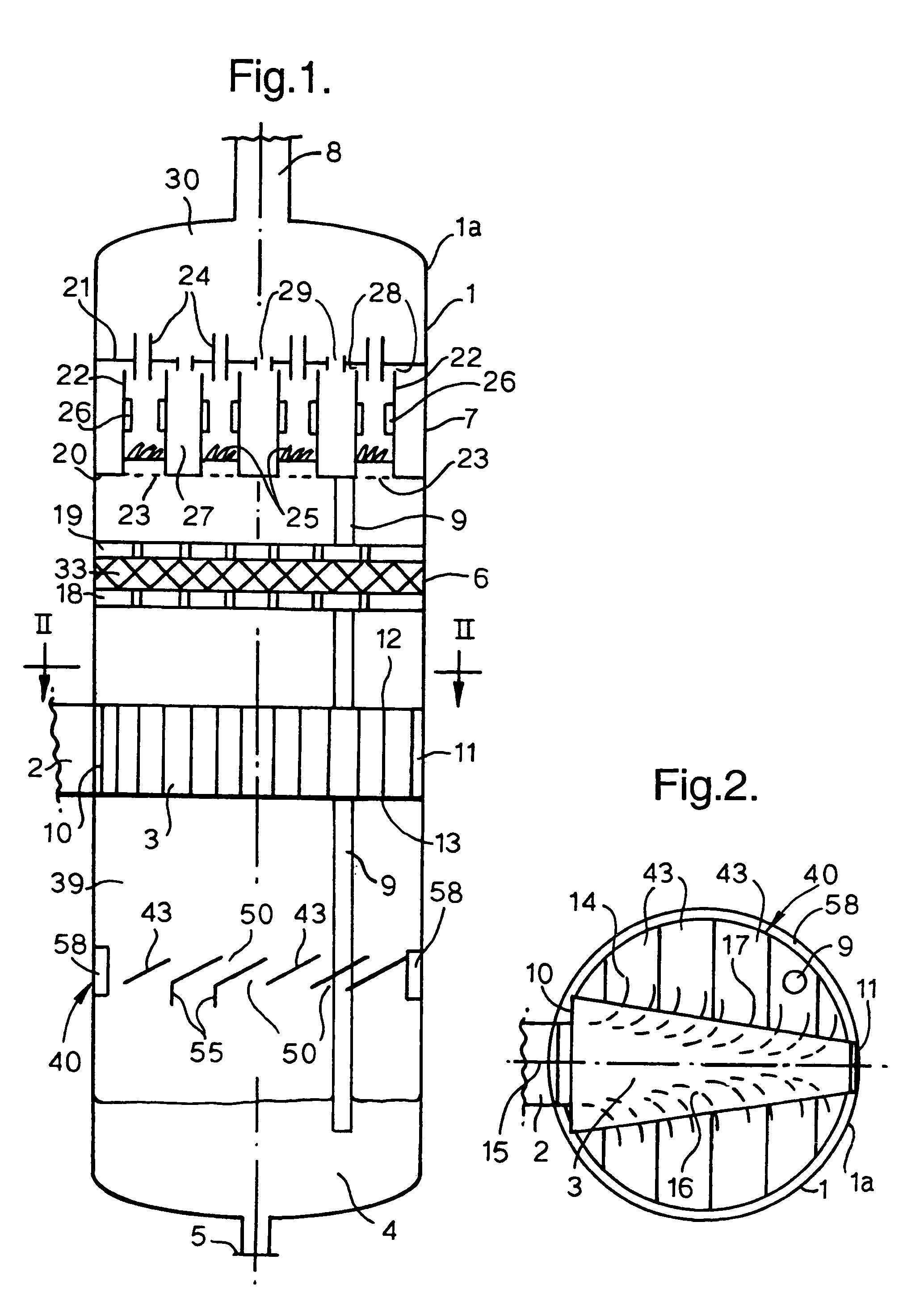
[0028]Reference is made to FIGS. 1 and 2, showing a gas / liquid separator 1a for separating a fluid comprising gas and liquid into a gas-rich stream and a liquid-rich stream. The separator 1a comprises a vertical cylindrical vessel 1 having an inlet nozzle 2 in the sidewall of the vessel 1.

[0029]The vessel 1 of the depicted embodiment of the invention comprises a gas / liquid separation device 3 having an inlet connected to the fluid inlet nozzle 2 and arranged at some distance above the lower part 4 of the vessel which functions as a liquid collecting space. The lower part 4 is provided with a liquid outlet 5.

[0030]At some distance above the primary gas / liquid separation device 3, a coalescer 6 is arranged. The coalescer 6 extends horizontally over the entire cross section of the vessel. At some distance above the coalescer is a further (secondary) gas / liquid separation device 7 arranged, which also extends over the whole cross section of the vessel. The secondary separator 7 is situa...


PUM

PropertyMeasurementUnit
velocitiesaaaaaaaaaa
diameteraaaaaaaaaa

Abstract

A gas / liquid separator comprising a vertical vessel having an inlet for a gas / liquid mixture; a gas / liquid separation device arranged within the vessel, which separation device has an inlet in fluid communication with the inlet of the vessel, and an outlet means for at least partially separated gas and liquid; an outlet for gas from the vessel, above and in fluid communication with the outlet means of the separation device; a liquid collection space in the vessel, below and in fluid communication with the outlet means of the separation device; and an outlet for liquid from the vessel, having a receiving end in the liquid collection space, wherein the gas / liquid separation device is a vane inlet device and wherein between the separation device and the liquid collection space a liquid collection promoter tray is arranged, forming a receiving area for liquid impinging on the tray from above and having a passage for liquid received on the receiving area to flow to the liquid collection space; and the use of such a gas / liquid separator.

Description

FIELD OF THE INVENTION[0001]The invention relates to a vertical separator vessel for separating a gas / liquid mixture. In particular the invention relates to such a vessel comprising an inlet for a gas / liquid mixture; a gas / liquid separation device arranged within the vessel, which separation device has an inlet in fluid communication with the inlet of the vessel, and an outlet means for at least partially separated gas and liquid; and which vessel further comprises an outlet for gas above and in fluid communication with the outlet means of the separation device; a liquid collection space below and in fluid communication with the outlet means of the separation device; and an outlet for liquid arranged to withdraw liquid from the liquid collection space.BACKGROUND OF THE INVENTION[0002]There are numerous examples in the petroleum and chemical industry where a gas / liquid mixture has to be separated. In many applications the mixture is a gas with a relatively small percentage of liquid ...

Claims


Application Information

Patent Timeline
Patent Type & Authority Patents(United States)
IPC IPC(8): B01D50/00B01D45/08B01D45/16
CPCB01D45/08B01D50/002B01D45/16B01D50/20
Inventor POLDERMAN, HUGO GERARDUS
Owner SHELL OIL CO
Why Eureka
Try Eureka