Force transmission element, window lifter and motor vehicle door with a window lifter

a technology of transmission element and lifter, which is applied in the direction of vehicle body, windows, monocoque construction, etc., can solve the problems of so-called glass drop and small size, and achieve the effect of small spacing and increased crash safety

Inactive Publication Date: 2009-10-06
FAURECIA INNENRAUM SYST
View PDF27 Cites 5 Cited by
  • Summary
  • Abstract
  • Description
  • Claims
  • Application Information

AI Technical Summary

Benefits of technology

[0020]In another aspect, the invention relates to a motor-vehicle door with a window lifter according to the invention. For example, an inside door panel of the motor-vehicle door has an opening which is used for receiving a support on which the drive and the deflection rollers of the window lifter are mounted. Because an especially compact construction of the window lifter is possible due to the force-transmission elements according to the invention, that is, the arrangement of deflection rollers with a relatively small spacing, the opening in the inside door panel can be relatively small accordingly. In this way, the stiffness of the motor-vehicle door and also the crash safety can be increased.

Problems solved by technology

A common disadvantage of previously known window lifters is that the maximum so-called glass drop, that is, the maximum travel of the window between a closed position and an open position, is smaller than the spacing of the deflection rollers of the window lifter.

Method used


Image

  • Force transmission element, window lifter and motor vehicle door with a window lifter
  • Force transmission element, window lifter and motor vehicle door with a window lifter
  • Force transmission element, window lifter and motor vehicle door with a window lifter

Examples


Embodiment Construction

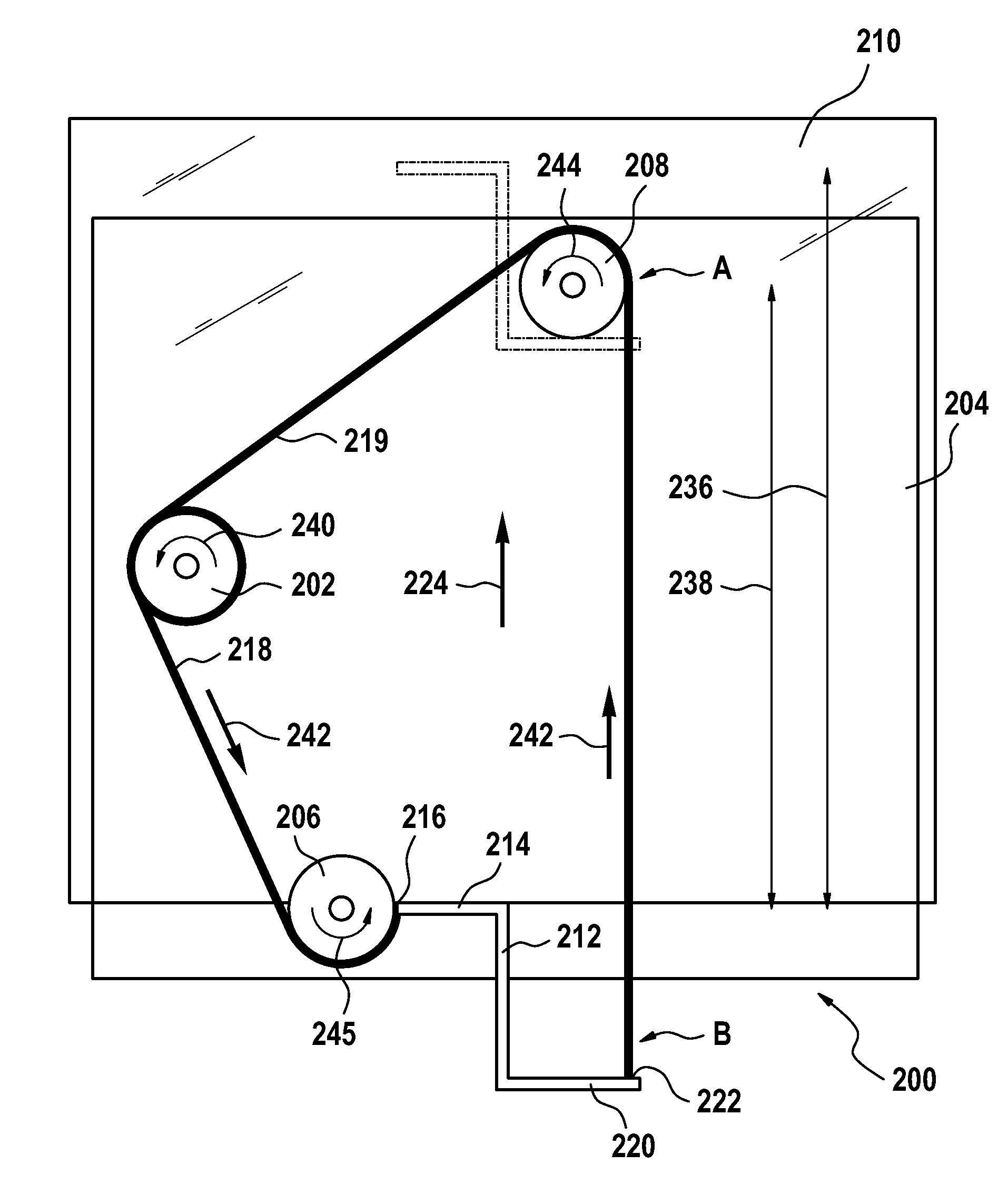
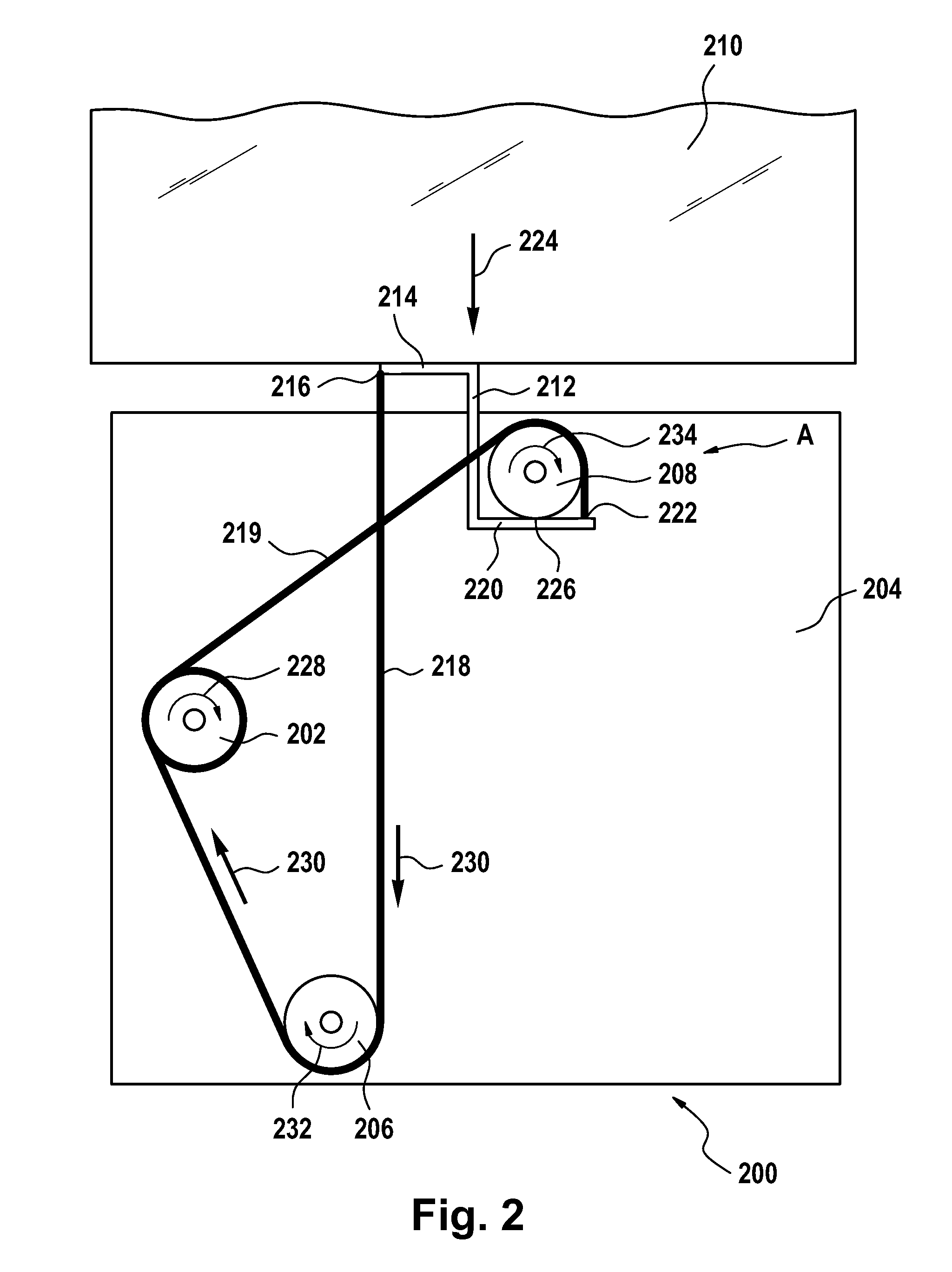
[0030]FIG. 2 shows a cable window lifter 200. The cable window lifter 200 has a drive, which drives a cable reel 202. The drive with its cable reel 202 is mounted on a support 204. The support 204 can involve a support panel such as an inside door panel, for example, or a plastic support, which, for example, is screwed to an inside door panel. The plastic support can form a so-called door module.

[0031]Furthermore, on the support 204 there are a lower deflection roller 206 and an upper deflection roller 208.

[0032]A window 210, which is to be displaced with the help of the cable window lifter 200, is shown in FIG. 2 in a completely closed position. The window 210 is connected rigidly to a force-transmission element 212. The force-transmission element 212 has an upper projection 214 with a force-application point 216 for a traction cable 218. The cable 218 is connected rigidly to the projection 214 at the force-application point 216.

[0033]The force-transmission element 212 has another ...


PUM


Abstract

The invention relates to a force-transmission element for a window lifter (200; 300; 500) for transmitting a closing force (242; 342, 356) and an opening force (230; 330, 350) to a window (210; 310; 510), wherein the force-transmission element has a first force application point (216; 316, 316′; 416) for transmitting the closing force and a second force application point (222; 322, 322′; 422) for transmitting the opening force, and wherein the force application points are arranged in a displacement direction of the window and offset perpendicular to this displacement direction.

Description

FIELD OF THE INVENTION[0001]The invention relates to a force-transmission element for a window lifter and also to a window lifter and to a motor-vehicle door with a window lifter.BACKGROUND OF THE INVENTION[0002]Various window lifters are known from the state of the art, like those from, for example, DE 197 23 642 B4, DE 102 30 073 A1, EP 1 129 875 B1, WO 2004 / 002766 A1, DE 196 19 087 C2, DE 102 52 055A1, WO 2004 / 065738 A1, and DE 102 55 461 A1.[0003]A common disadvantage of previously known window lifters is that the maximum so-called glass drop, that is, the maximum travel of the window between a closed position and an open position, is smaller than the spacing of the deflection rollers of the window lifter. This is clarified in FIG. 1 as an example for a window lifter known from the state of the art:[0004]FIG. 1 shows a cable window lifter 100, which is fixed to a support panel 102 of a motor-vehicle door. The support panel 102 involves the inside door panel of the motor-vehicle ...

Claims


Application Information

Patent Timeline
Patent Type & Authority Patents(United States)
IPC IPC(8): E05F11/48
CPCE05F11/486E05F11/488E05Y2900/55E05Y2201/642
Inventor HUGE, CARSTENMANGOLD, CLAUS
Owner FAURECIA INNENRAUM SYST
Why Eureka
Try Eureka