Backlight unit and liquid-crystal display device using the same
a liquid crystal display and backlighting technology, applied in lighting and heating apparatus, planar/plate-like light guides, instruments, etc., can solve the problems of insufficient luminance of white light obtainable by a white led for emitting white light or a set of three leds for emitting red, green and blue monochromatic light, and achieve the effect of reducing color unevenness on the display screen
- Summary
- Abstract
- Description
- Claims
- Application Information
AI Technical Summary
Benefits of technology
Problems solved by technology
Method used
Image


Examples
first embodiment
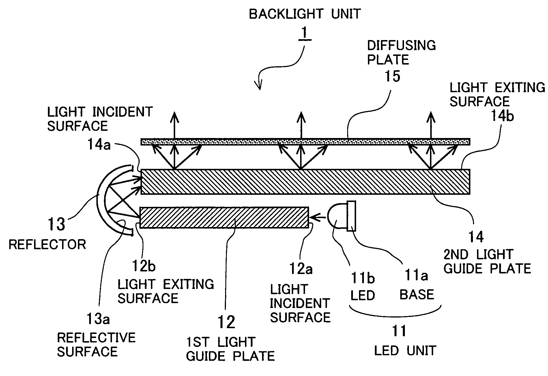
[0061]FIGS. 2 and 3 schematically show the configuration of a backlight unit 1 according to a first embodiment of the present invention.
[0062]As shown in FIGS. 2 and 3, the backlight unit 1 according to the first embodiment, which is of the edge-light type, comprises a LED unit 11 into which a plurality of LEDs 11b are incorporated as point-shaped light sources. The unit 1 further comprises a rectangular first light guide plate 12, an approximately hemicylindrical reflector 13, a rectangular second light guide plate 14, and a rectangular diffusing plate 15. These optical members are fixed by a housing or frame (not shown) to have the configuration shown in FIG. 3.
[0063]Each of the LEDs 11b of the LED unit 11 emits red, green, or blue monochromatic light. These LEDs 11b are aligned and fixed on a base 11a at equal intervals in a predetermined order or sequence. The base 11a is formed by a belt-shaped rigid plate. For example, the LEDs 11b are aligned from one end of the base 11a (i.e...
second embodiment
[0082]FIG. 4 schematically shows the configuration of a backlight unit 1A according to a second embodiment of the present invention.
[0083]The backlight unit 1A of the second embodiment has the same configuration as the backlight unit 1 of the first embodiment of FIGS. 2 and 3 except that optical filters 21a and 21b are selectively formed on the light exiting surface 12b of the first light guide plate 12, instead of the optical filters 20a and 20b formed on the light incident surface 14a of the second light guide plate 14 in the first embodiment. Therefore, explanation about the same configuration as the backlight unit 1 according to the first embodiment is omitted here by attaching the same reference numerals as those of the first embodiment to the same or corresponding elements.
[0084]In this way, like the backlight unit 1 according to the first embodiment, the backlight unit 1A according to the second embodiment comprises the LED unit 11 with the LEDs 11b emitting red, green and bl...
third embodiment
[0087]FIG. 5 schematically shows the configuration of a backlight unit 1B according to a third embodiment of the present invention.
[0088]The backlight unit 1B has the same configuration as the backlight unit 1 according to the first embodiment of FIGS. 2 and 3 except that optical filters 22a and 22b are selectively formed on the planar light exiting surface 14b of the second light guide plate 14, instead of the optical filters 20a and 20b formed on the light incident surface 14a of the second light guide plate 14 in the first embodiment. Therefore, explanation about the same configuration as the backlight unit 1B according to the third embodiment is omitted here by attaching the same reference numerals as those of the first embodiment to the same or corresponding elements.
[0089]With the backlight unit 1B, as shown in FIG. 5, the filter 22a that limits or controls the transmission of the green light is selectively formed at or near the left-side end of the light exiting surface 14b o...
PUM
 Abstract
Description
Claims
Application Information