System for measuring turbulence remotely

a technology of turbulence measurement and remote measurement, applied in the field of meteorological sensors, can solve the problems of affecting the comfort of passengers, passengers avoiding flying, and the inability to detect or predict clear air turbulence using current technology, so as to improve the accuracy of turbulence measurement, improve the availability of transmitted signals, and improve the coverage of the atmosphere

Active Publication Date: 2009-10-06
THE BOEING CO
View PDF43 Cites 63 Cited by
  • Summary
  • Abstract
  • Description
  • Claims
  • Application Information

AI Technical Summary

Benefits of technology

[0007]Other preferred embodiments are adapted for use on land and marine vehicles and include velocity sensors such as inertial measurement units that enable the receiver to adjust the turbulence measurement to account for the motion of the vehicle. In the alternative, the system can include an input for receiving velocity information from the vehicle. These vehicle-adapted systems can determine velocity-induced phase shifts and Doppler effects from the velocity of the vehicle and remove these effects from the measured variations of the signal. Also, the system can include an input to receive the heading of the vehicle to enable the system to determine the direction to each GPS satellite currently in view. The direction can be determined relative to the aircraft heading or relative to the ground (or Earth). Further, the system can adjust the measured turbulence estimate for crosswind effects (i.e. apparent turbulence introduced into the measurement because of the motion of the receiver relative to the turbulent volumes of air). Moreover, signals from more than one satellite constellation (e.g. GPS, GLONASS, and Galileo) can be used by the receiver to make the measurements. Using more than one constellation improves the availability of transmitted signals, gives better coverage of the atmosphere, and improves the accuracy of the turbulence measurements. The turbulence measurements can be conveyed to end users such as the aircrew, air traffic controllers or computers, or other aircraft. The forms in which the turbulence measurements can be conveyed include audible alarms, overlays of turbulence intensity on aircrew station displays, or overlays of turbulence intensity on a map. Thus, airlines operating in accordance with the principles of the present invention will provide smoother flights with fewer occurrences of passengers being advised to return to their seats because of the possibility of turbulence. Moreover, the number of times when the advisories are based on inaccurate predictions (e.g. “false alarms”) will be reduced. Likewise, detours of aircraft around turbulence will be avoided thereby reducing fuel consumption.
[0008]In a second preferred embodiment, the present invention provides a receiver of electromagnetic energy (that travels along a path that is subject to turbulence). The receiver includes an input, an output, and a circuit in communication with the input and the output. The input receives a first signal that is representative of the electromagnetic energy as it is received. The circuit accepts the first signal and a second signal that is representative of a velocity of a mobile platform. Also, the circuit adjusts the first signal using the second signal to determine an alteration of the electromagnetic energy caused by the turbulence thereby eliminating alterations caused by the velocity of the mobile platform. In a preferred embodiment, the circuit determines the alteration caused by only the tropospheric turbulence. The output generates a third signal that is representative of the turbulence.

Problems solved by technology

Clear air turbulence significantly affects the comfort of passengers on commercial aircraft and has even caused some would be passengers to forego flying due to their fears associated with the turbulence.
Because clear air turbulence can occur with little or no warning, the passengers tend to stay in their seats with their seat belts fastened.
While much turbulence (e.g. the turbulence associated with thunderstorms) can be predicted or detected, clear air turbulence can not be detected or predicted by currently available technology.
While meteorological maps provide flight crews some indication of where turbulence might be expected, these maps are not perfect.
First, they tend to become stale within hours and are based on underlying meteorological models that are far from perfect also.
Additionally, turbulence occurs across a wide variety of geometric scales.
In the absence of any better approach, the aviation industry has created a system in which the pilots of each aircraft radio in reports of the clear air turbulence that they encounter on their routes, or “airways.” Subsequent aircraft flying the same airway can maneuver in response to these reports but risk encountering turbulence along their detour.
Likewise, those aircraft on unplanned detours such as when an airport is too busy to accept arrivals, or is otherwise shut down (by for example severe weather), will have no way to foresee the turbulence along the route.

Method used


Image

  • System for measuring turbulence remotely
  • System for measuring turbulence remotely
  • System for measuring turbulence remotely

Examples


Embodiment Construction

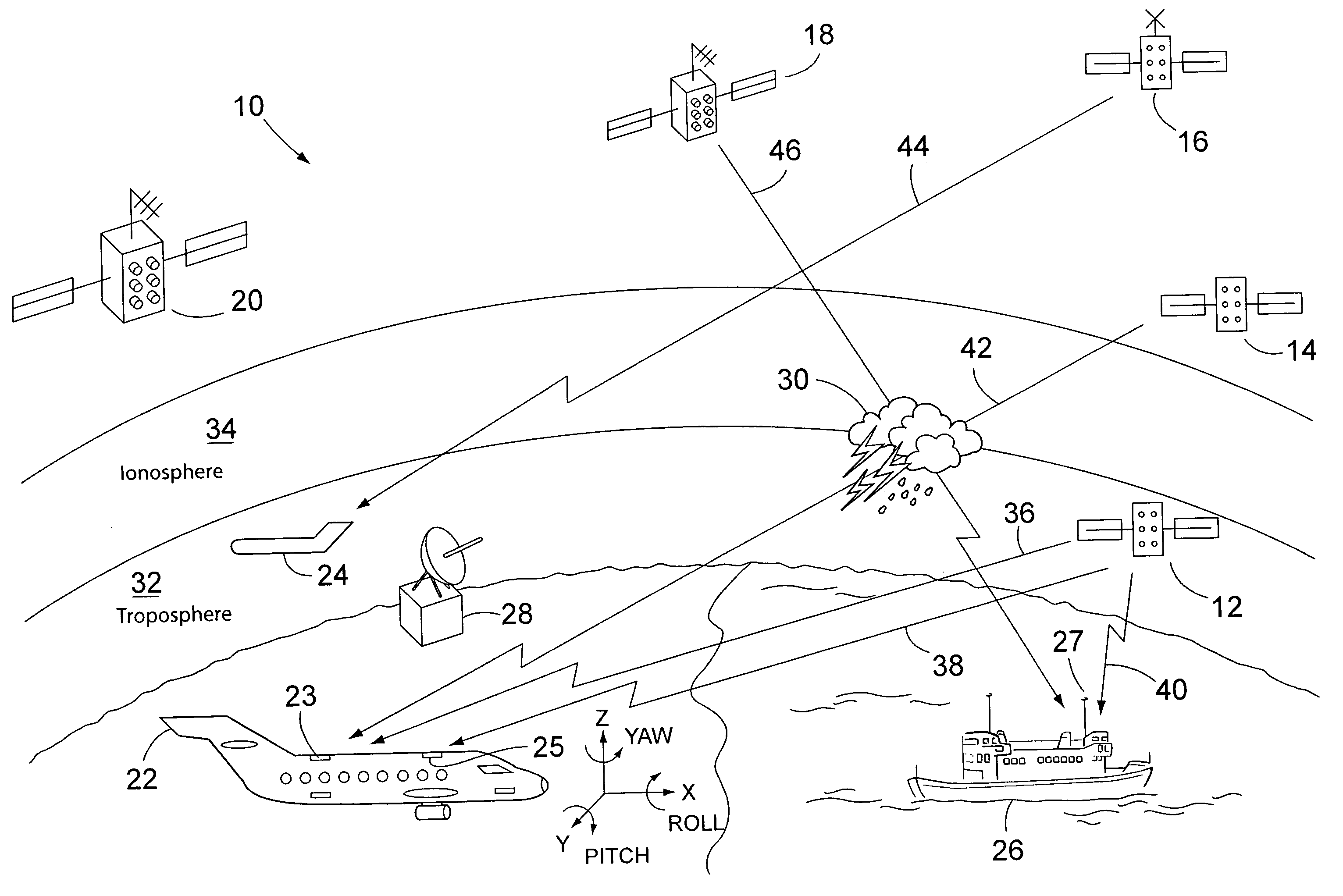
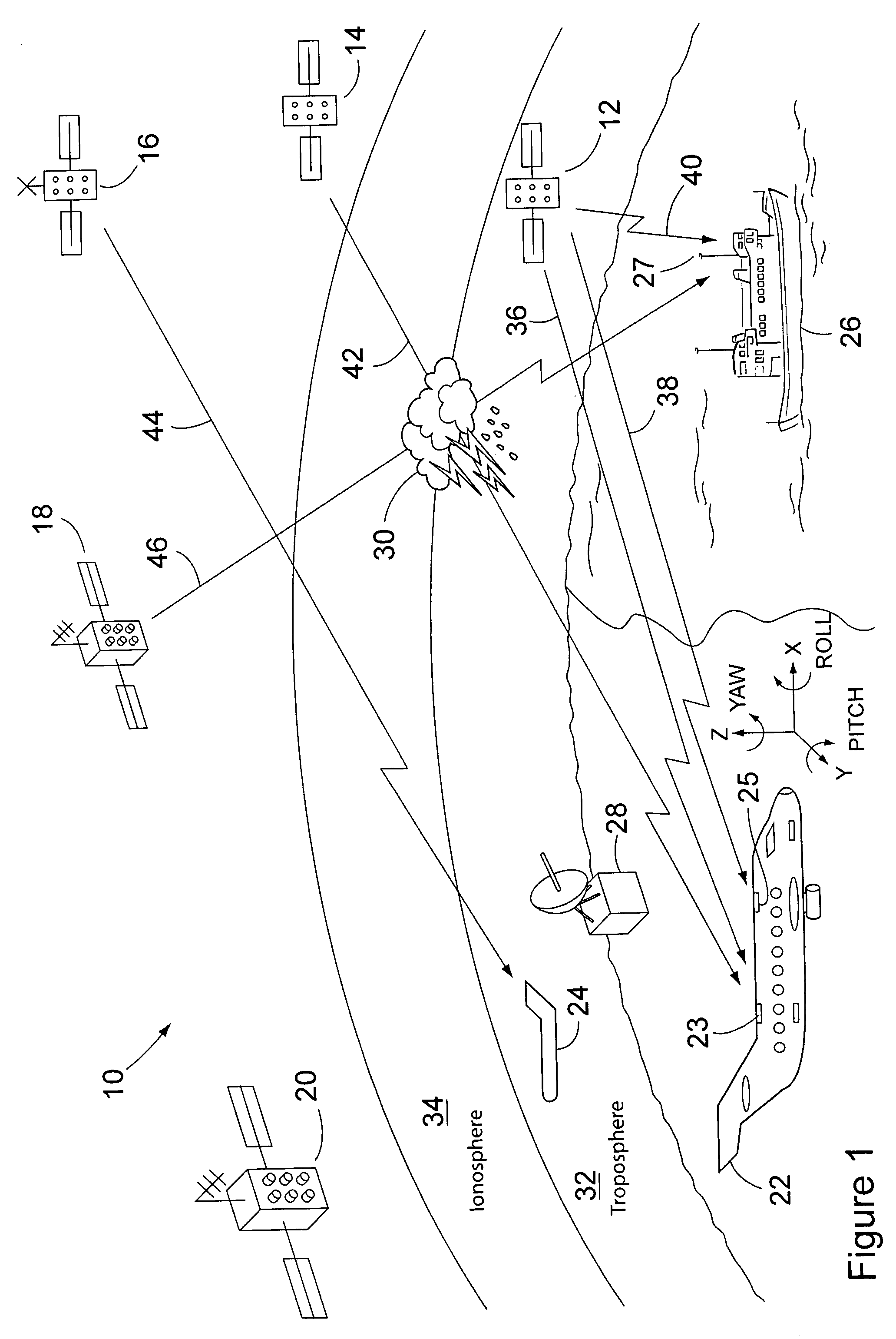
[0019]Many modern aircraft use radio positioning signals broadcast from satellites (e.g. GPS or GLONASS) for navigation. Atmospheric turbulence can cause the GPS receivers to occasionally lose lock with the signals by corrupting, or altering, the signal to an extent sufficient to render the receiver temporarily inoperative. The problem becomes more pronounced when the transmitting satellite, as seen by the receiver, nears the horizon. Not only does the signal have to traverse a significantly longer path through the atmosphere, but the signal path is likely to penetrate deeply into the troposphere where turbulence can be much more pronounced than in the higher portions of the atmosphere. Also, as the signal path nears the ground, multipathing can occur which further degrades the signal quality. Because turbulence has previously been seen as a problem to be avoided, the receiver antennas are typically configured to reject signals with low elevation angles relative to the horizon.

[0020...


PUM


Abstract

A system and method for detecting turbulence includes several mobile platforms, a mobile platform velocity sensor, and several electromagnetic energy transmitters and receivers. The receivers receive the energy transmitted by the transmitter(s) after it has traveled along a path subject to the turbulence. The receivers detect alterations of the energy caused by the turbulence and filter the alterations for effects of the mobile platform velocity (on which either a transmitter or receiver is located). Additionally, the system may create a three-dimensional model of the. In another preferred embodiment, the present invention provides a method of detecting turbulence using a mobile platform. The method includes receiving electromagnetic energy that has traveled along a path subject to the turbulence and determining the alteration to the energy caused by the turbulence. The alterations are filtered of the effects of the velocity of the mobile platform on which the receivers are preferably located.

Description

FIELD OF THE INVENTION[0001]This invention relates generally to meteorological sensors and, more particularly, sensors that sense clear air turbulence remotely.BACKGROUND OF THE INVENTION[0002]Clear air turbulence significantly affects the comfort of passengers on commercial aircraft and has even caused some would be passengers to forego flying due to their fears associated with the turbulence. Because clear air turbulence can occur with little or no warning, the passengers tend to stay in their seats with their seat belts fastened. At times, though, every passenger must get up for comfort and physiological reasons. Therefore, if the aircraft must proceed through the turbulence, it would be useful if the aircrew could alert the passengers to the disturbance before the aircraft encounters it.[0003]Preferably, the aircraft would avoid the turbulence altogether but even that preventative measure requires that the turbulence be detected or predicted before it occurs. While much turbulen...

Claims


Application Information

Patent Timeline
Patent Type & Authority Patents(United States)
IPC IPC(8): G01S1/08G01S19/14
CPCG01P5/001G01W1/16G01S13/955G01P5/26G01W2001/003Y02A90/10G08G5/0021G08G5/0091
Inventor TILLOTSON, BRIAN J.SPINELLI, CHARLES B.
Owner THE BOEING CO
Why Eureka
Try Eureka