Light-emitting device, driving support system, and helmet

a technology of driving support system and light-emitting device, which is applied in the direction of organic semiconductor devices, polarising elements, navigation instruments, etc., can solve the problems of low power consumption, thin, lightweight, and light-emitting devices

Inactive Publication Date: 2009-10-06
SEMICON ENERGY LAB CO LTD
View PDF92 Cites 50 Cited by
  • Summary
  • Abstract
  • Description
  • Claims
  • Application Information

AI Technical Summary

Benefits of technology

[0022]According to the invention, a light emitting device is fabricated by using an active matrix substrate provided with TFTs, through which a far side of the display device can be seen. The light emitting device according to the invention includes a light emitting element comprising a cathode and an anode that are made of a highly transparent material, and an organic compound layer sandwiched between them. The light emitting device of the invention is thin, lightweight, and consumes low power. Since the light emitting device of the invention is transparent or translucent, a visual image superposed on a front scene can be displayed, so that safe driving is realized even when it is installed on a dashboard.
[0030]The use of chaos enables to detect the change in mental and physical conditions of a driver quickly and a warning is given to call the driver's attention. In order to prevent a driver from falling asleep at the wheel, for example, a driving support system using chaos that gives a warning when a chaos attractor becomes simple, namely before the driver falls asleep at the wheel is more effectively used than a simple driving support system that gives a warning only after the period with driver's eyes closed from the start of sleeping exceeds a certain period.
[0040]In the case of a vehicle having a small frontspace around a driver's seat such as a motorcycle and a snowmobile, a light emitting device is installed in a helmet. The light emitting device for helmet is structured so that a far side of the device can be seen. A light emitting device having an organic compound layer as a light emitting layer can display a high resolution image such as navigation data and is advantageous in its lightweight and compactness compared with the other display devices. A projection display device requires a light path for projection, which is difficult to be provided in a limited space inside a helmet even when a mirror and the like are used. Besides, in the projection display device, a projected image may be disturbed in many cases due to the water drop when it rains.
[0047]According to the invention, a display can be switched within the forward sight of a driver, thus the driver can view displayed data safely while keeping his eyes ahead at the wheel.

Problems solved by technology

The light emitting device of the invention is thin, lightweight, and consumes low power.

Method used


Image

  • Light-emitting device, driving support system, and helmet
  • Light-emitting device, driving support system, and helmet
  • Light-emitting device, driving support system, and helmet

Examples


embodiment 2

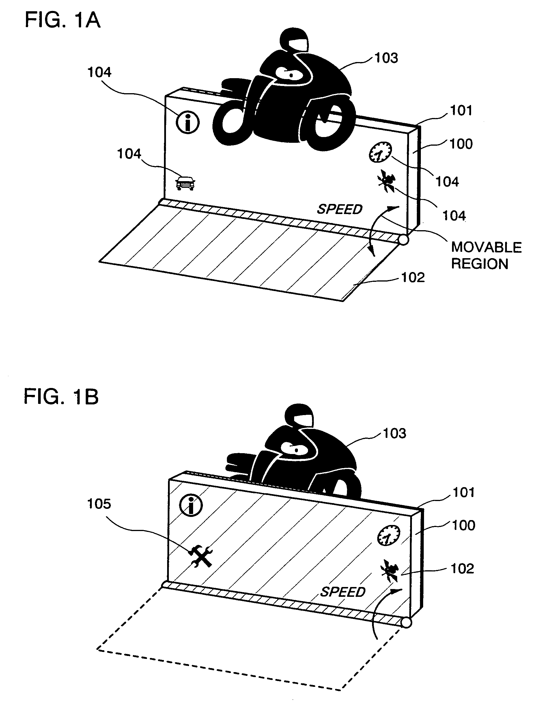
[0110]FIG. 5A shows a functional configuration (configuration means) of a driving support system of this embodiment.

[0111]A GPS 413 receives a location signal with respect to the present location such as latitude and longitude data from a satellite using an antenna, a receiver, a transmitter, and the like, and then it reads out either or both of the detected signal and the location signal in order to measure the present location.

[0112]FIG. 5B shows a functional block which configures the GPS. The functional block of the GPS includes a System Control, a Memory IF (Memory Interface), a PMU (Path Memory Unit), a UART (Universal Asynchronous Receiver / Transmitter system), an FCC, a DSP IF Buffer (DSP (Digital Signal Processor) Interface Buffer), an RFC IF (Radio Frequency Choke coil Interface), an ADC IF (A-D converter Interface), an STI Logic (Set Interrupt Logic), and the like.

[0113]Note that two different pieces of the above functional block may be connected to each other using a glue...

embodiment 3

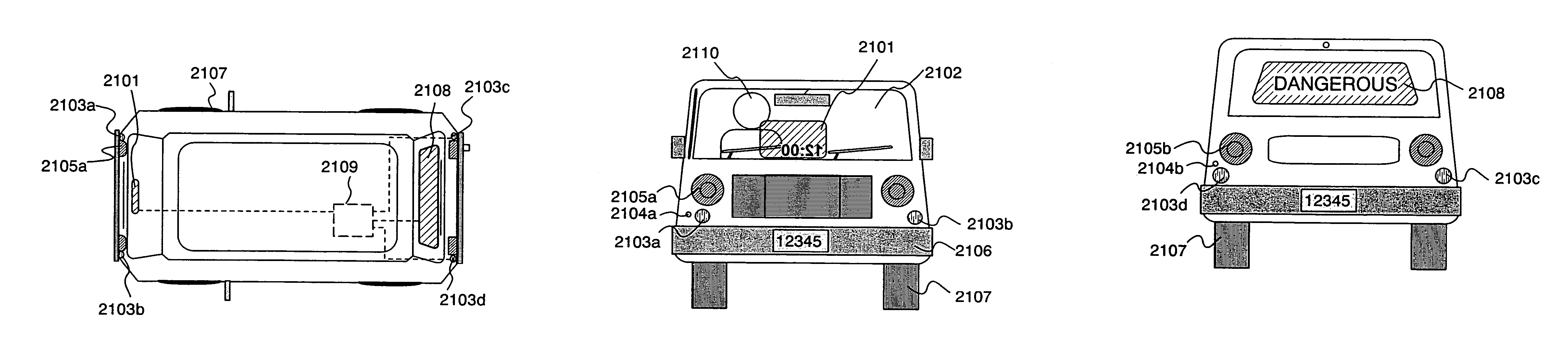
[0136]FIG. 7A shows an example of fabricating a light emitting device (of a dual emission structure) having a light emitting element including an organic compound layer as a light emitting layer, over a substrate having an insulating surface.

[0137]FIG. 7A is a top plan view of a light emitting device. FIG. 7B is a cross sectional view taken along a line A-A′ in FIG. 7A. Portions surrounded by dotted lines 1101, 1102, and 1103 denote a source signal line driver circuit, a pixel portion, and a gate signal line driver circuit respectively. Reference numeral 1104 denotes a transparent sealing substrate and 1105 denotes a first sealing material. A portion surrounded by the first sealing material 1105 is filled with a second transparent sealing material 1107. Note that the first sealing material 1105 includes a gap material for securing space between substrates.

[0138]Reference numeral 1108 denotes a wiring for transmitting signals between the source signal line driver circuit 1101 and the...

embodiment 4

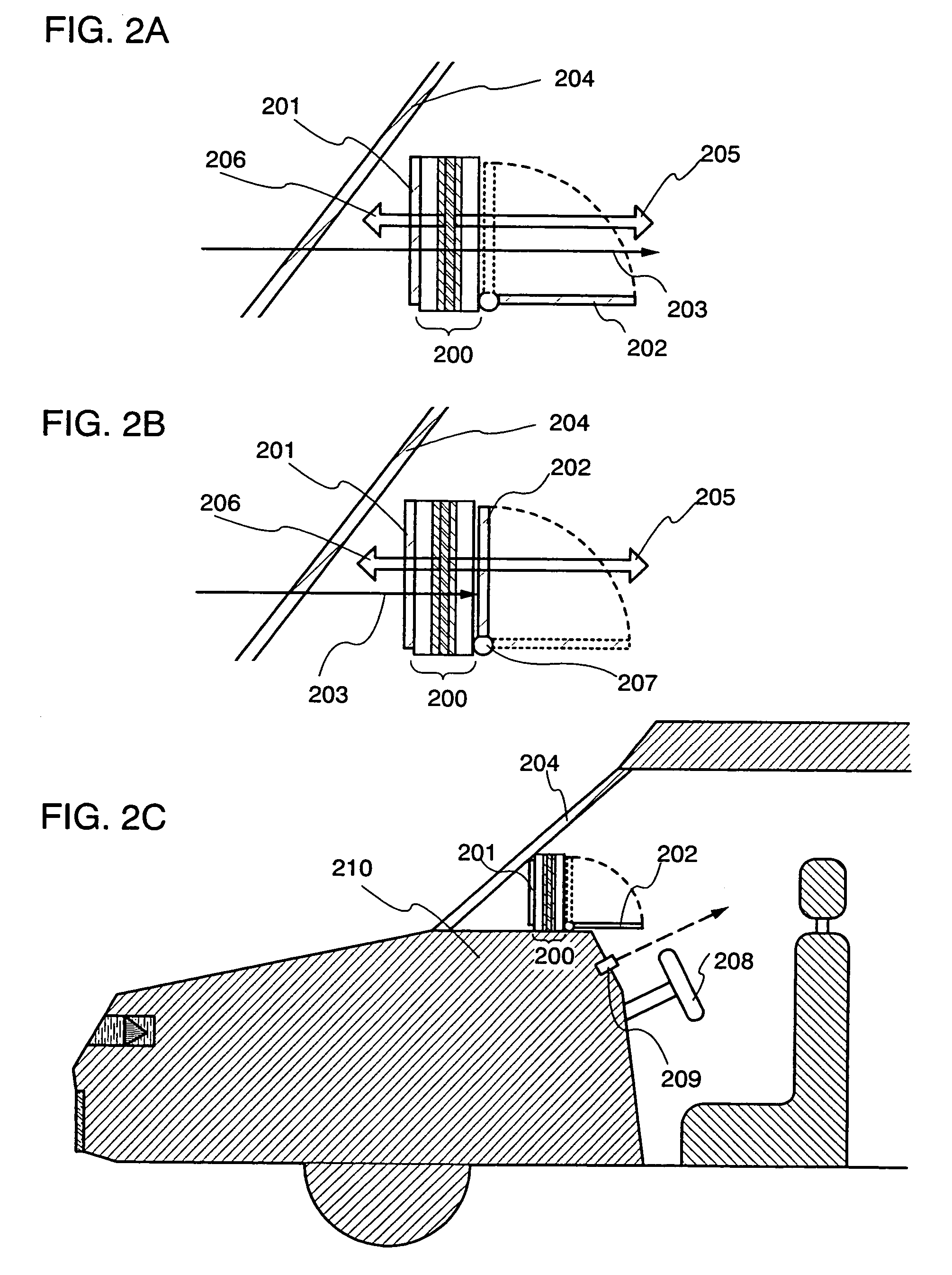
[0159]In this embodiment, FIGS. 8A and 8B show helmets each installed a light emitting device. In the case of a vehicle having small frontspace around a driver's seat such as a motorcycle and a snowmobile, a light emitting device is installed in a helmet. The light emitting device can display with high resolution such as map data and is advantageous in its lightweight and compactness compared with the other display devices. The projection display device requires a light path for projection, which is difficult to provide in a limited space inside vehicle even when a mirror and the like are used.

[0160]FIG. 8A is a side view of a helmet to which a light emitting display device 704 is mounted. FIG. 8B is a side view of the helmet. In FIGS. 8A and 8B, reference numeral 701 denotes a helmet body, 702 denotes a shield, 703 denotes a part for attaching the shield.

[0161]The light emitting display device 704 mounted on the helmet is structured so that a far side of the display can be seen, an...


PUM

PropertyMeasurementUnit
transmittanceaaaaaaaaaa
thicknessaaaaaaaaaa

Abstract

It is an object to provide a driving support system and a display device suitable for the driving support system. According to the driving support system, change in driver's mental and physical conditions can be caught instantaneously and a warning light emission display is given within the forward sight of the driver in order to call the driver's attention. A light emitting device of the driving support system can display a far side of the display. A display may be switched between a transmission mode and a non-transmission mode by adjusting a movable polarizer.

Description

BACKGROUND OF THE INVENTION[0001]1. Field of the Invention[0002]The present invention relates to a driving support system installed in various mobile objects such as a car and a motorcycle, and in particular, the invention relates to a display device suitable for a driving support system, a helmet provided with a display device, and a driving support system including a display device.[0003]2. Description of the Related Art[0004]In recent years, driving support systems for various mobile objects (car, motorcycle, plane, and the like) have been actively developed aiming for improvement of driving as to safety and comfort. ‘Adaptive Cruise Control System’ has already been produced by using a driving environment sensing technology, which is a driving support system for controlling the constant speed drive, for controlling car following the preceding vehicle (for controlling a distance between cars).[0005]In addition, for example, disclosed in Patent Document 1 is a technology of detecti...

Claims


Application Information

Patent Timeline
Patent Type & Authority Patents(United States)
IPC IPC(8): G05D1/00G06G7/78G01C21/00A42B3/00B60K35/00B60R1/00B60W40/02G01C21/36G02B5/30G02B27/01G02F1/13G08G1/0969G09F9/00G09G3/00G09G3/06G09G5/00H01L27/32H01L51/50H01L51/52H05B33/00H05B33/02H05B33/14
CPCG02B27/01B60W40/02B60W40/08B60W50/14G01C21/365G02B27/017G02B27/0172H01L51/5281B60W30/095B60K28/06B60W2540/22B60W2550/402G02B5/30H01L27/3244H01L2251/5323B60W2556/50B60W2540/221H10K59/12H10K50/86H10K2102/3031B60K35/00H05B33/00
Inventor YAMAZAKI, SHUNPEIKOYAMA, JUNKUWABARA, HIDEAKI
Owner SEMICON ENERGY LAB CO LTD
Why Eureka
Try Eureka