Increasing the range of access point cells for a given throughput in a downlink of a wireless local area network

a wireless local area network and access point technology, applied in the field of wireless communication, can solve the problems that the beamforming design under the conventional tp constraint may not be directly applicable, and achieve the reduction of the total power and significant performance degradation, significant performance degradation, and the effect of reducing the total power

Inactive Publication Date: 2009-10-06
WSOU INVESTMENTS LLC +1
View PDF25 Cites 149 Cited by
  • Summary
  • Abstract
  • Description
  • Claims
  • Application Information

AI Technical Summary

Problems solved by technology

This means that the beamforming designed under the conventional TP constraint may not be. directly applicable in the countries with the EIRP-based regulation.
However, one fundamental disadvantage in such a SMRB approach is that in some propagation conditions the averaged antenna pattern may result in sharp peaks leading to a corresponding reduction of the total power and significant performance degradation.
One fundamental disadvantage to the SEB approach set forth above is that narrow-band EIRP optimization may be a poorly defined (i.e., close to a singular problem), especially for a case with relatively low number of antennas, leading to a significant performance degradation.

Method used


Image

  • Increasing the range of access point cells for a given throughput in a downlink of a wireless local area network
  • Increasing the range of access point cells for a given throughput in a downlink of a wireless local area network
  • Increasing the range of access point cells for a given throughput in a downlink of a wireless local area network

Examples


Embodiment Construction

[0031]Illustrative embodiments of the invention are described below. In the interest of clarity, not all features of an actual implementation are described in this specification. It will of course be appreciated that in the development of any such actual embodiment, numerous implementation-specific decisions may be made to achieve the developers' specific goals, such as compliance with system-related and business-related constraints, which will vary from one implementation to another. Moreover, it should be appreciated that such a development effort might be complex and time consuming, but may nevertheless be a routine undertaking for those of ordinary skill in the art having the benefit of this disclosure.

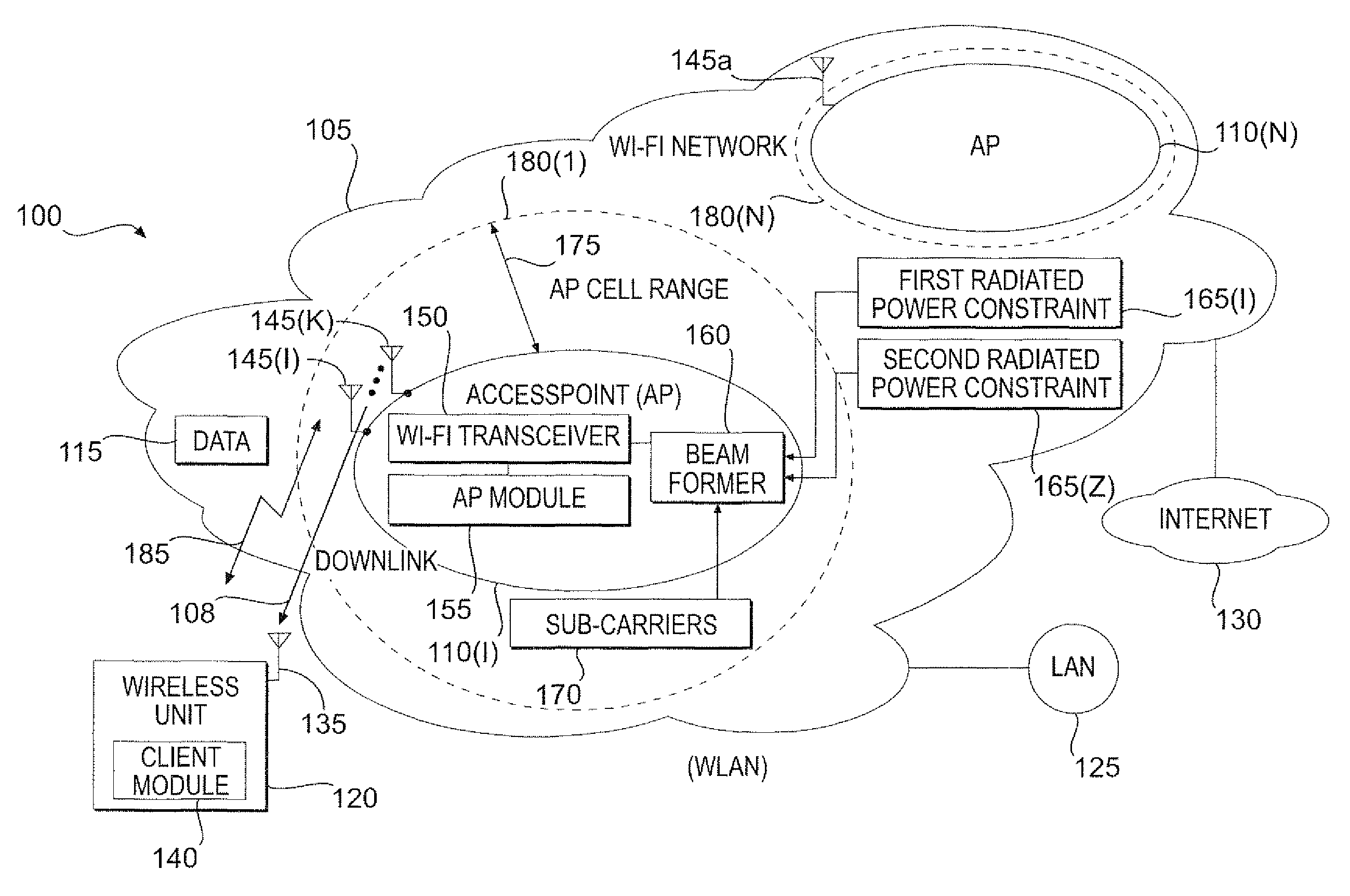
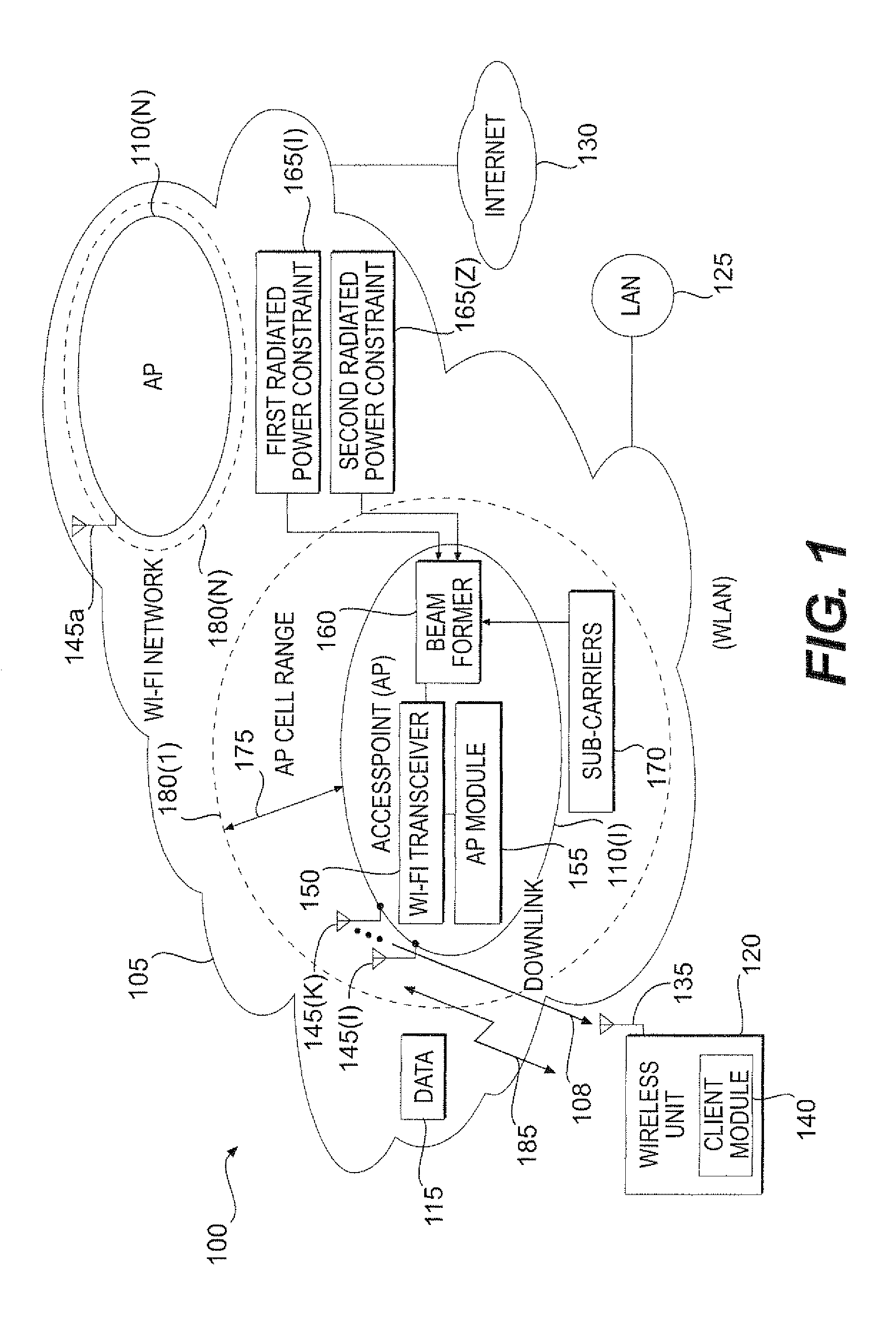
[0032]Generally, a method and an apparatus are provided for transmitting data in a downlink of a plurality of access point cells in a wireless local area network (WLAN) to increase the range of the downlink for a given throughput under one or more radiated power constraints. A plu...


PUM


Abstract

The present invention provides a method and an apparatus may increase or extend the range of wireless communication cells for a given throughput in a downlink of a wireless communication system. When transmitting data in a downlink of a plurality of access point cells in a wireless local area network (WLAN), the range of the downlink may be increased for a given throughput under one or more radiated power constraints. The method includes providing a plurality of antennas at an access point to transmit the data to a wireless unit under at least one of a first and a second radiated power constraints. The method further includes using the plurality of antennas for beamforming over a group of sub-carriers subject to the first and / or second radiated power constraints. Under one or more radiated power constraints, a multiple antenna based beamforming may extend the range of a wireless communication for a user of a wireless unit that may be located within a coverage area across the plurality of access point cells of a Wi-Fi network associated with the WLAN. A joint beamforming optimized over all of sub-carriers may account for a European regulation restriction into at least one of an averaged and a spectral density Equivalent Isotropic Radiated Power (EIRP) constraint. In this way, an Orthogonal Frequency-Division Multiplexing (OFDM) based joint beamformer may provide a significant performance improvement and range extension.

Description

FIELD OF THE INVENTION[0001]This invention relates generally to telecommunications, and more particularly, to wireless communications.DESCRIPTION OF THE RELATED ART[0002]Wireless communications systems or mobile telecommunication systems typically provide different types of services to different users or subscribers of wireless communication devices. A wireless local area network (WLAN) generally includes one or more access points (APs) that can establish wireless communications links with wireless units. A wireless communications link between a wireless unit and an access point (AP) may use an uplink from the wireless unit to the access point and a downlink in the reverse direction.[0003]To establish the wireless communications link for a connection or session, the access point typically includes radio transceivers to transmit and receive radio frequency signals. Over the uplink, signaling information and user information may be received over the air interface at an access point. O...

Claims


Application Information

Patent Timeline
Patent Type & Authority Patents(United States)
IPC IPC(8): H04M1/00
CPCH04B7/0691H04B7/0617
Inventor KUZMINSKIY, ALEXANDR
Owner WSOU INVESTMENTS LLC
Why Eureka
Try Eureka